To complete this tutorial you will require the Input / Output module.
Note: This tutorial cannot be completed using LISCAD Lite.
Aim
The aim of this tutorial is to continue the examination of XSL Style Sheets, extending the concept of the LISCAD XML User Interface, by introducing filter controls to the Interface.
In this tutorial, we will create a style sheet that will select all Lines in a SEE database that belong to a certain Group and have a certain maximum length. We will output these Lines to a HTML document, displaying the points that the Line joins, the type of Line, the length of the Line and the Azimuth.
Firstly, we will introduce a control that allows the user great flexibility to select certain entities from a SEE database file according to the attributes of these entities.
We need to be able to display within LISCAD some sort of dialog screen with OK and Cancel buttons and some control which will store the points the user has selected, so that when the user clicks on the OK button, the report will be produced. We saw in the previous tutorial "XSL Style Sheets - Interface Controls" that the <Dialog> element was to be used for this purpose. To find out about other controls, we will refer to the LISCADXML-SEEDE-1.0 Schema document. You can find the LISCADXML-SEEDE-1.0.html" file on the LISCAD installation CD in the "XML Documentation" folder, or it can be downloaded from the LISCAD web site at http://www.listech.com/liscad/library.aspx?library=miscellaneous.
Before you begin
Select this button to install the required data files.
- Understanding the Line Filter Control
Open the "LISCADXML-SEEDE-1.0.html" file by double clicking on it. It should open automatically in your default web browser.
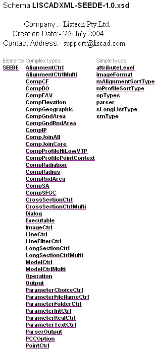
Click on the SEEDE element link.
Click on the Dialog element link.
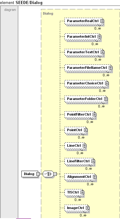
Click on the LineFilterCtrl link.
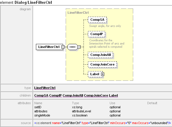
This is the interface control we will use to filter the lines. It has similar attributes to the Point Control we looked at in the previous tutorial, so we are familiar with how they work.
Click on the CompJoinAll link.

Click on the CompJoinAll link under Type.

This information tells us that using this element will extract for us the Line Scale Factor and arc-to-chord correction information between points along a line. This is of use to us here.
- Create a Basic Report of All Lines in the Data Set
Included in this tutorial is a very basic style sheet which will output the code of all the Lines in a SEE database. We will use this style sheet as a starting point for developing what we wish to do in this tutorial.
In LISCAD, Select File/Open and open the "XSL Interface Controls.see" file.
Select Tasks/Utilities, then Report/XSL Filter Controls Tutorial. If this option is not available in the Reports Menu, use the Add/Remove function to add it to the list.
Enter the following into the edit fields.
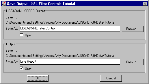
Click OK.
Here is our Sample All Lines report.
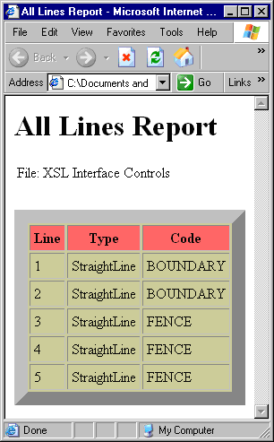
- Review the Style Sheet That Created This Report
Open the REP XSL Filter Controls Tutorial.xsl file in your style sheet editor, in this case Cooktop.
You will notice, looking at the code, that it is very similar to the basic Points List that we saw in the tutorial "Stylesheets - An Introduction". The basic differences are that the opType attribute for the <Operation....> element is "allLines", instead of "allPoints", and instead of there being a template which matches on "Point", there is one that matches on "StraightLine".
If you look up the LISCADXML-SEEDB-1.0 Schema documentation, under SEEDB, then Lines, you will see that there are many types of Lines in LISCAD. These types of Lines are represented by different child elements for the <Lines> element.
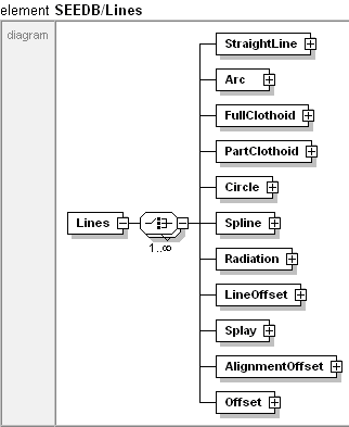
This style sheet contains a template that matches on "StraightLine". This means that it will be applied to any <StraightLine..../> elements in the XML data. The example SEE database file here contains only "StraightLine" types of lines, so this is fine in this case. However, there are no templates that match on "Arc" or "Spline" or any of the others, so this style sheet would not output any details on any Lines which weren't of the "StraightLine" type.

Another thing to note is that the second <xsl:value-of..../> element has a value of its select attribute of "name(.)". This syntax in XSL means that it will return the name of the element itself. In this case, it will always be "StraightLine", since we are only matching on elements that are <StraightLine..../>. Although it may not be particularly useful here, this can be a very handy function in XSL language when we don't know specifically what the name of an element is.
- Place a Line Filter Control on the Dialog Box
Now, let's edit the style sheet to incorporate a line filter control. As in the previous tutorial, where we incorporated the Point Control, replace the <UI> and <Operation..../> elements code with the following block...
<Dialog display="1">
  <Title>
    <Text value="Line Filter Dialog"/>
  </Title>

  <LineFilterCtrl setID="1" attributes="core">
    <Label>
      <Text value="Line Filter:"/>
    </Label>

    <CompJoinAll/>
  </LineFilterCtrl>

  <UI>
    <Text>
Select the line filter you wish to apply from the drop down list.
Selecting [None] will use all lines in the data file.

To create a new line filter select [None] and press the Edit Filter button.
To edit an existing filter select the filter then press the Edit Filter button.
    </Text>
  </UI>
</Dialog>
Also change the heading title from "All Lines Report" to "Filtered Lines Report".
<head>
  <title>Filtered Lines Report</title>
</head>
<body>
  <h3>Filtered Lines Report</h3>
- Using the Line Filter Control
Save the style sheet and go back to LISCAD and select the Report/XSL Filter Controls Tutorial report again. If you have entered the Dialog instructions correctly the following dialog should appear.

Click Edit Filter
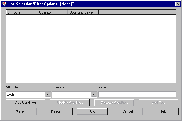
This dialog allows us to set up a filter to select only certain lines. We shall now create a filter which will allow us to return only the Lines that belong to the Group TITLE.
In the Attribute: drop down list, select Group. In the Operator: drop down list, select Equals. In the Value(s): box, type TITLE.
Click the Add Condition button. What we have done here is specify a "Condition". A filter is made up of one or more Conditions. The Condition we have added is where the Group equals "TITLE", hence it will find all Lines which belong to a Group called TITLE.
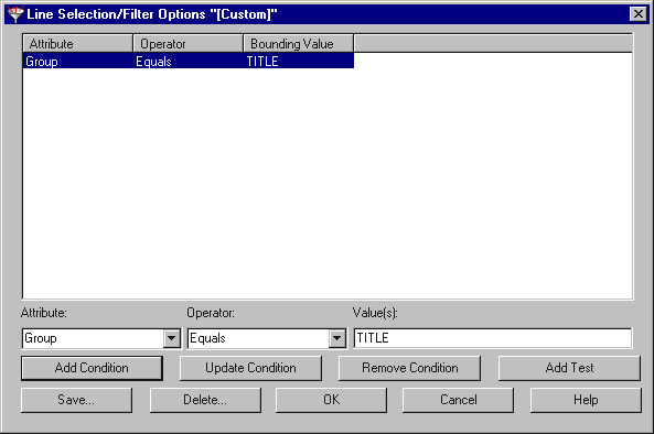
Click the Save button. In the Filter name edit field, type "My Line Filter".
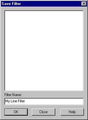
Click OK.
This has now saved the Filter under the name My Line Filter. This means that whenever LISCAD is run on this machine, anywhere you are asked for a Line Filter, the option of My Line Filter will be available, regardless of which SEE database you are working on.
Click OK to close the Line Selection/Filter Options dialog.

- Create the Filtered Report
Click OK
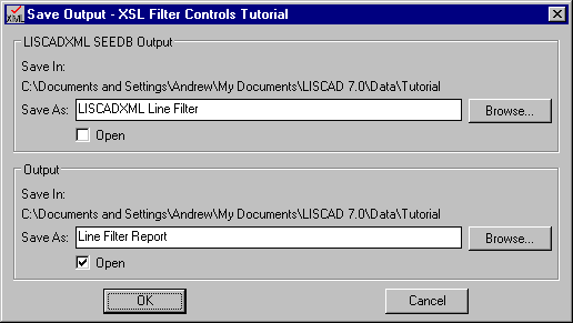
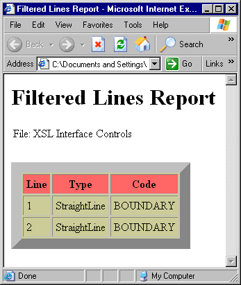
Outputting to HTML again, we get a report with only those Lines that belong to group TITLE.
- Retrieve Additional Line Information and the Points Associated
With the Selected Lines
Now we have seen how to use the Line Filter to select the Lines we are interested in. Just seeing the Code of a Line is not very interesting, let's bring back more information for each line.
We shall get the Group (to confirm that the Filter is working correctly!), the From and To Points and their respective coordinates, the azimuth of the Line and the ground distance of the Line.
The azimuth for a Line is given by:
plane bearing - forward arc-to-chord correction - grid convergence at the From PointThe ground distance for a Line is given by:
plane distance / ground scale factorWith this is mind, what data did we get output to the LISCADXML file? Examine this to find out.
To do this, open up the LISCADXML Line Filter.xml file in your web browser. It will look the same as the "Line Filter Report.html" initially. In your browser select View/Source, to open the Source up in Notepad. Within the Notepad file, comment out the second line of the XML, which refers to the style sheet we are using. If you are unfamiliar with this procedure, review the previous couple of tutorials in which this method has been documented.
Save the Source, and refresh your web browser Window. The XML elements should now be displayed.
Scroll down to the <Lines> element.
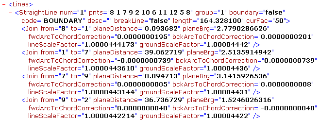
We see that because we added the child element <CompJoinAll/> to the Line Filter Control element, we also get <Join..../> child elements for the <StraightLine..../> elements.
This provides us with the Point From and To references for each Line Segment, the plane distance, bearing, arc-to-chord corrections, Line Scale Factor and Ground Scale Factor for each line segment. However, we are missing the Grid Convergence at each of the terminal points for the Line.
From the tutorial "Style Sheets - User Interface and Helper Files", we saw that we could get the Grid Convergence for a Point by including the <CompSFGC/> child element for the Point Selection element. The only problem is, we are returning Lines here, not Points, there are no <Point..../> elements in the Raw XML data file.
This is not a big problem in reality. We need to return all the Points used by the Lines selected in the Line Control Filter, ensuring that we include a <CompSFGC/> child element to give us the Grid Convergence.
Study the following code block and add it to the Style Sheet in the XSL editor after the <Dialog> element code.
    <Operation opType="getPoints" useIDs="1" attributes="core">
        <CompSFGC/>
    </Operation>
Thus...

Note that the <Dialog> element still contains the Line Filter Control element. The Line Filter control element has a ID of "1", set with the SetID attribute. After the <Dialog> element, we have added a <Operation....> element, with an opType of "getPoints". This is different to what we saw before, where it was set to "allPoints". In this case, we use "getPoints" and we also set the useIDs attribute to "1". This is telling LISCAD to get the Points from the Control of ID "1", which was the Line Filter Control. In other words, return all the Points that are referenced by the Lines returned by the Line Filter Control, which could be quite different to getting all Points in the database. We are also saying that we only want LISCAD to return the core attributes for those Points, and we also want LISCAD to return the attributes computed via the <CompSFGC/> element, of which the Grid Convergence is one.
Note: IDs can be alphanumeric and of unlimited length, but must not contain spaces. They must be unique for each dialog, but to avoid potential confusion it is best to make them all unique.
Save the style sheet and go back to LISCAD, run the Line Filter Report again to create a new "LISCADXML Line Filter.xml" file. Open this file and scroll down to the <Points> section, which should now be included.
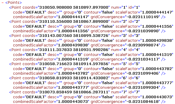
We can see now how the added <Operation....> element has added the relevant points for the Lines returned.
Study the <StraightLine..../> elements again in the LISCADXML file and take a look at the group attribute. Note that the group attributes are numbers, e.g. "1", but if we go to LISCAD and select Display/Groups, we see that indeed, there are no Groups with numbers, no Group called "1".
The reason for this is that the group attribute refers to the num attribute of a Group.
Scroll up to the <Groups> element. This is the collection of <Group..../> elements which have a name attribute and a num attribute. So if a <Line..../> element has a group attribute of "1", then to find out what group name it has, we need to refer to the <Group..../> elements, looking for the Group with the num attribute of "1". The name attribute of this would refer to the name of the Group we are familiar with in LISCAD, namely in this case "TITLE".

Keeping this in mind, we can continue editing the style sheet to output the information to HTML, knowing that we have all the data we need in the LISCADXML file.
- Format the Report
Return to the XSL editor, and find the code which sets up the HTML table headers. Add the new table headers to accommodate the new information to be displayed.
<table BGCOLOR="#CCCC99" border="15" CELLPADDING="4">
    <tbody>
        <tr>
            <th bgcolor="#FF6666">Line</th>
            <th bgcolor="#FF6666">Type</th>
            <th bgcolor="#FF6666">Code</th>
            <th bgcolor="#FF6666">Group</th>
            <th bgcolor="#FF6666">From</th>
            <th bgcolor="#FF6666">East</th>
            <th bgcolor="#FF6666">North</th>
            <th bgcolor="#FF6666">To</th>
            <th bgcolor="#FF6666">East</th>
            <th bgcolor="#FF6666">North</th>
            <th bgcolor="#FF6666">Azimuth</th>
            <th bgcolor="#FF6666">Ground Dist.</th>
        </tr>
        <xsl:for-each select="/SEEDB/Lines/*">
            <xsl:apply-templates select="."/>
        </xsl:for-each>
    </tbody>
</table>
While we are here, we should also update the Notes instructions, by editing what is inside the <UI><Text> elements.

Note: Getting the format of the Notes to look right in the dialog takes a bit of trial and error. Due to the different fonts used in the editor and the dialog boxes it is not always possible to get the layout to look correct in both. To line columns up in the dialog it is best to separate items using Tabs rather than spaces. Although the above code taken from the Cooktop editor does not look the best it is fine in the dialog, which is more important.
- Output the Attributes of the Line
Now we need to add the code that will give us the Group name for each Line. The code will be added to the template matching "StraightLine", since the group attribute belongs to the <StraightLine..../> element itself. For every <StraightLine..../> element, we need to get the group value, and visit the <Group..../> element which has a num attribute of that value. Finding this, we wish to return the name attribute for that element. All this can be done in one line of code.
<xsl:value-of select="/SEEDB/Groups/Group[@num=current()/@group]/@name"/>
This says return the value of the name attribute of the SEEDB/Groups/Group element which has a num attribute of value equal to the current element's group attribute.
The function current() is common XSL language which returns the current element. Placed in the style sheet, this should make more sense.
Note: The current() node can also be represented by ".". However we need to use current() when equating an attribute e.g. @num=current()

- Output the Points Within the Line
The rest of the information we need though has to do with the line segments of the lines, referred to by the <Join....> child elements. Hence, for each <StraightLine....> element, we need to loop through each of its <Join....> child elements, extracting the data we need from each, and outputting to HTML.
To do this, add a <xsl:for-each....> loop and within the for-each loop we will call a template which will match on each <Join....> element.
    <xsl:for-each select="child::Join">
        <xsl:apply-templates select=".">
            </xsl:apply-templates>
    </xsl:for-each>
Thus...

The syntax child::Join in XSL simply refers to the child element called <Join....>. We could also have used the "/" symbol, i.e. "/Join".
We haven't yet got a template to match on "Join", so we need to add one now. Scroll down to the end of the file and include the following code block just above the closing </xsl:stylesheet> tag.
<xsl:template match="Join">
        <tr>    <td/><td/><td/><td/>
        </tr>
    </xsl:template>
This includes a template match on "Join", which means that every time a <Join..../> element is found, the code within this block will be performed. The HTML tags are in order to prepare the table. We wish to leave the first four columns alone when we add the Point data, since we have already populated them with previous data.
Add code that will add the Point From ID to the document
<td align="right"><xsl:value-of select="/SEEDB/Points/Point[@num = current()/@from]/@id"/></td>
Thus...

This code returns the id attribute of the point which has a num attribute equal to the from attribute of the current <Join....> element.
This highlights an important distinction which users of LISCAD may be unaware of. A Point in a SEE database will have an ID value, which the user would be well aware of. A Point however, also has a hidden numerical value which must be unique in the database for each point. The user does not get to see this number, nor edit it. It just so happens that in the example SEE database file we are using here, the numerical value of the Point, stored in the num attribute is the same as the ID of the Point, stored in the id attribute.
Feel free at any stage in the next few steps to save the style sheet and test it through LISCAD to see what the HTML document will look like as you go.
Add code that will add the Point From coordinates to the document. In the previous tutorial, we looked at Helper Files and some generic functions that helped us return the Easting and Northing of Points. We will use these functions again here, passing to them the coord attribute of the point which has a num attribute equal to the from attribute of the current <Join..../> element.
<td align="right">
    <xsl:call-template name="GetFormattedEast">
        <xsl:with-param name="xyz" select="/SEEDB/Points/Point[@num = current()/@from]/@coords"/>
        <xsl:with-param name="format" select="'0.000'"/>
    </xsl:call-template>
</td>

<td align="right">
    <xsl:call-template name="GetFormattedNorth">
        <xsl:with-param name="xyz" select="/SEEDB/Points/Point[@num = current()/@from]/@coords"/>
        <xsl:with-param name="format" select="'0.000'"/>
    </xsl:call-template>
</td>
Now repeat the above code, changing the reference from the "from" point to the "to" point to add the "to point id" and coordinates.
- Output the Information Joining the Points
We now need to add just the azimuth and the ground distance of the Lines to the document.
The azimuth for a Line is given by:
plane bearing - forward arc to chord direction - grid convergence at the From PointAgain, in the last tutorial, we saw a function that converted radians to degrees minutes and seconds for us. We will use this again, since the plane bearing, arc-to-chord directions and grid convergence are all output to XML in radians.
The code to output azimuth is thus...
<td align="right">
    <xsl:call-template name="RadsToRoundedDMS">
        <xsl:with-param name="angleInput" select="./@planeBrg - ./@fwdArcToChordCorrection - /SEEDB/Points/Point[@num = current()/@from]/@gridConvergence"/>
        <xsl:with-param name="angleRF" select='0.0000048481368110953599358991410235795'/>
        <xsl:with-param name="performFormat" select="'1'"/>
    </xsl:call-template>
</td>
Here we are sending the value of the plane bearing minus the arc to chord correction minus the grid convergence of the From Point to the RadsToRoundedDMS function. We are also asking for the answer to the nearest second, and asking for the degrees symbol ° to be output too.
The ground distance for a Line is given by
Plane distance / ground scale factorThe code to output the ground distance is thus...
<td align="right">
    <xsl:value-of select="format-number(./@planeDistance div ./@groundScaleFactor , '0.000')"/>
</td>
Note the use of the div operator here to do a division. In XSL, the "/" symbol, which you might expect would be the operator to do a division, is of course used to represent a child element, as we saw earlier in this tutorial.
The full code in the template matching on "Join" is

Make the changes to the style sheet and save the file.
- Run the Report
In LISCAD, use File/Open to open the "XSL Interface Controls.see" file.
Select Tasks/Utilities, then Reports/XSL Filter Controls Tutorial. If this option is not available in the Reports Menu, use the Add/Remove function to add it to the list.
Select the Filter "My Line Filter" from the list.

Click OK.
Enter the following into the prompts.
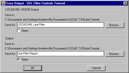
Click OK.
We have a report with all the data we wish to see on it.
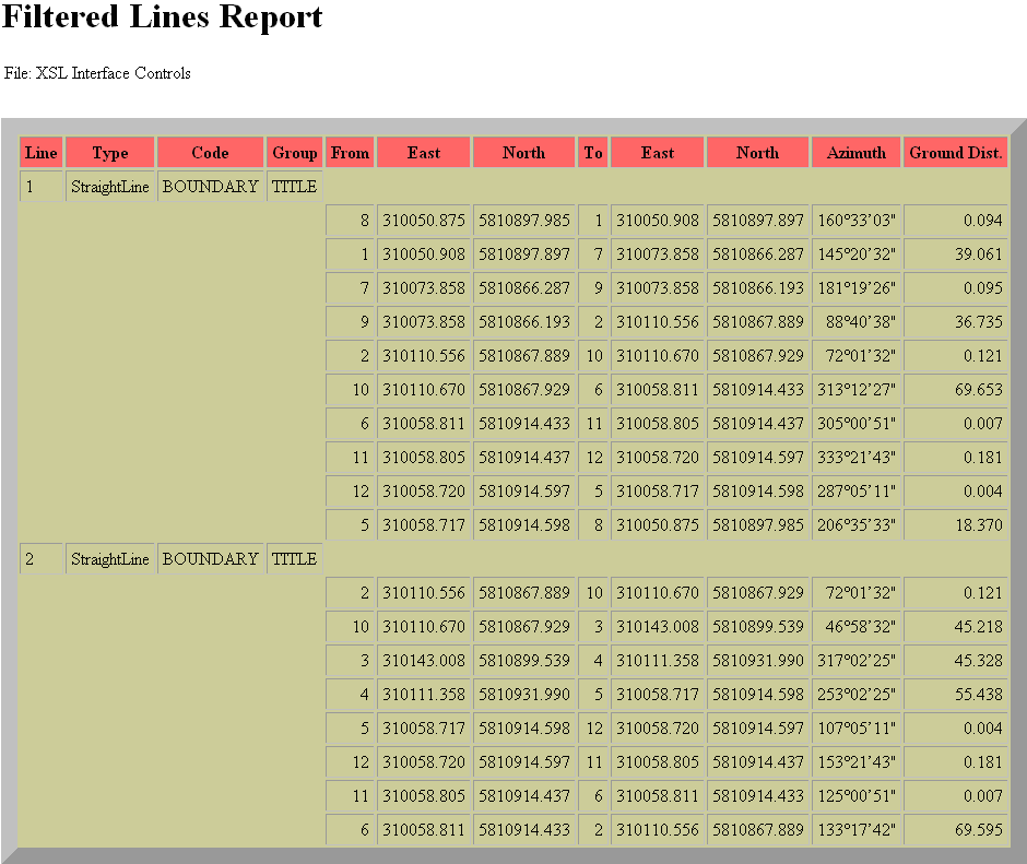
- Apply a Line Length Filter
There's still a little more to do however. We wanted to filter on a maximum line length. This is because we can see that the SEE file has a few anomalies to it. Some of the line segments are very small, less than 1 metre long, due perhaps to digitizing errors. We wish to highlight these errors, only producing a report which shows these small lengths.
Run the report through LISCAD again, but when you get to the Line Filter screen, select the "My Line Filter" filter and click the Edit Filter button.
We wish to add a filter that returns all Lines that have a length less than 1 metre, AND also belong to the TITLE Group.
Select Length in the Attribute: drop down list, < in the Operator: list and type 1.00 in the Value(s): box.
Click Add Condition.
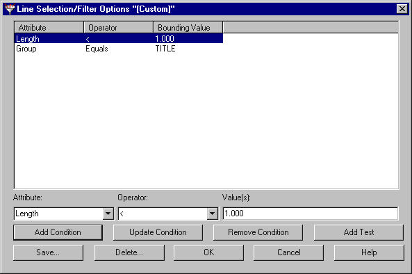
Click Save, Click on "My Line Filter", then Click OK.
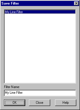
We have now modified the filter to include lines less than 1 metre in length.
Click OK to close the Line Selection/Filter Options dialog.
Click OK on the Line Filter Dialog.
Enter the same output names in the Save XML Output dialog we used previously and press OK.

What happened to the Lines? Shouldn't we have got back only those lines less than 1 metre?
The problem is that the Length criterion in the Filter applies to the whole length of the Line, not individual Line segments.
To get around this we could go back to LISCAD and segment all the lines to make them individual line segments. Then the report would work as envisaged. However, to finish this tutorial, we will look at a way of modifying the style sheet to save us from having to edit the SEE file itself.
To do this, let's just think about what we are doing in this style sheet. Initially, when we match on the root node at the start, we are setting up some HTML to display headers and a table, which is populated when the template that matches on the <StraightLine..../> element is called. We then complete the population of each table row by calling a template that matches on the <Join..../> element. In this <Join..../> element, an attribute stores the length of the line segment between two points in the overall Line. Therefore, if we only want to see a report that displays line segments less than one metre long, we need to have some mechanism that looks at the length of the line segment and determines whether it should be output.
XSL provides us with the <xsl:if....> conditional test. In an earlier tutorial, we have seen how the <xsl:choose> could be used to test a statement and branch to different code depending upon whether the statement was true or false. The <xsl:if....> element is similar, except that it doesn't allow branching. It encloses a block of code and that block will only be performed if the test statement for the <xsl:if....> is true.
We can use this to screen out whether to carry out the transformation defined by the template that matches on "Join", the template that outputs the distance and bearing of individual line segments, by putting an <xsl:if....> around the template call.
Add the <xsl:if....> like this...

The test string is test="./@planeDistance <'1.00'".
Note that the < syntax is XSL for the "less than" operator. Conversely, if the operator was >, that would mean "greater than". The ">" or the "<" is not valid here, since there are already used to enclose element tags.
Save the style sheet.
We should be finished editing it now, so you can close the editor if you desire.
Re-run the export through LISCAD, but edit the filter before running the report.
Select the Length condition with the mouse to highlight it.
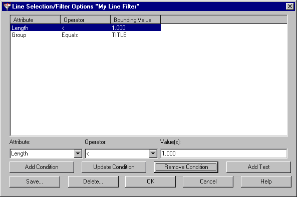
Click Remove Condition. The condition will disappear.
Save the filter, close the Line Selection/Filter Options dialog and run the report as before.
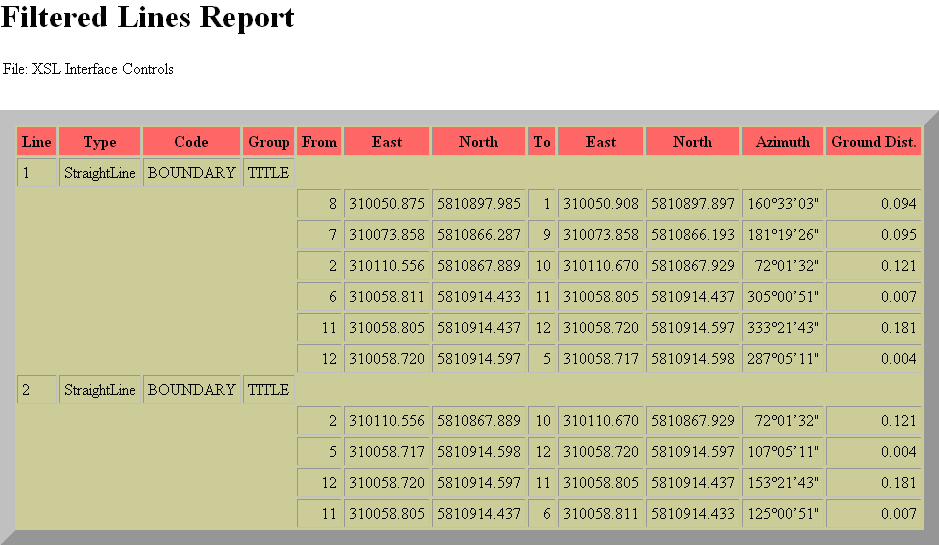
Finally! We have the filtered report, showing only those line segments less than 1 metre in length.
This tutorial has provided a look at how the user can create line filters in LISCAD using XSL Style sheets. We have learnt how to filter Lines to report on in a SEE database.
What happens if we want to change this 1 metre tolerance? Do we have to modify the style sheet each time? In the next tutorial "XSL Style Sheets - Using Parameter Controls" we will look at how we can allow the user to set tolerances from a dialog within LISCAD, so they don't have to modify the style sheet if they wish to search for lines less than another minimum length.
Conclusion
You have now completed the Tutorial on the XSL Style Sheets - Interface Filter Controls and should have a good understanding of the following:
- Creating a filter to extract certain elements from LISCAD to XML;
- Line selection Controls;
- Familiarization with XSL language function current();
- Helper File Functions.