To complete this tutorial you will require the Input / Output module.
Note: This tutorial cannot be completed using LISCAD Lite.
Aim
The aim of this tutorial is to continue the examination of XSL Style Sheets, developing the concept of the LISCAD XML User Interface, by showing how to add user controls to the Interface.
In the previous tutorial "XSL Style Sheets - User Interface and Helper Files", we saw how the report "XSL User Interface Tutorial" Style Sheet was used to produce a HTML document that displayed a list of all the points, codes, descriptions, coordinates, scale factors and grid convergences in a SEE database. In this tutorial we will edit the Style Sheet to control what Points are actually selected in the Report.
Firstly, we will introduce a control that allows the user to select certain points in a SEE database file by accepting them with the mouse and only output those points to the LISCADXML file.
Obviously we need to be able to display within LISCAD some sort of dialog box with OK and Cancel buttons and some controls which will the user to select the required points, so that when the user clicks on the OK button, the appropriate report will be produced. The first place to look for something that may provide this functionality to the user is in the LISCADXML-SEEDE-1.0 Schema document, introduced in the previous tutorial. You can find the "LISCADXML-SEEDE-1.0.html" file on the LISCAD installation CD in the "XML Documentation" folder, or it can be downloaded from the LISCAD web site at http://www.listech.com/liscad/library.aspx?library=miscellaneous.
Before you begin
This tutorial builds on the previous tutorial "XSL Style Sheets - User Interface and Helper Files". If you have not familiarized yourself with the previous tutorial, it would be wise to do this before attempting this one, since knowledge of the concepts introduced there are assumed in this tutorial.
Press this button to install the required data files.
- Creating a User Interface Dialog Box
Open the LISCADXML-SEEDE-1.0.html file by double clicking on it. It should open automatically in your default web browser.
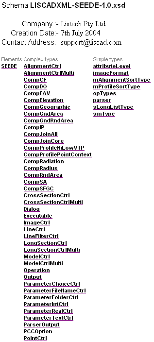
Click on the SEEDE element link.
Click on the Dialog element link. This is the element that will enable us to display a dialog on the screen.
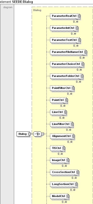
This has taken us to the documentation for the Dialog element, note the attributes of the element.

The attribute isUnbounded gives the LISCAD end user the ability to repeat an input process an unlimited number of times. In this case we only require a single instance of this dialog so we don't need to specify the isUnbounded attribute as the default is false. As a result, the second hasCounter attribute is also unimportant to us as the counter is only really useful to keep track of how many times the input process has been repeated. Feel free to experiment with these attributes at some stage though. If you wish to see an example of a case where the LISCAD end user has the ability to repeat the input process, run the "Ledder Diagram" report which allows for the input of an unlimited number of Reference Lines and multiple point selections for each Reference Line.
The third attribute, display, is a required attribute and is used to order the dialogs displayed in the interface.
How do we give a dialog a Title, some text that will be displayed along the top of the dialog window?
The Dialog element has a child element called Title.
Click on the Title element link.
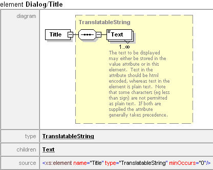
Note that the Title element also has a child element called Text.
Click on the Text element link.
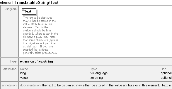
This tells us that we can store text as a value attribute of the Text element, or as a value of the element itself.
- Creating a Multilingual User Interface
The reason for this approach is to enable style sheets to be written that can be multilingual. This may be important if you are writing a style sheet that could be universally used on computers configured for other languages. If a style sheet is multilingual it will detect which language LISCAD is set to and attempt to load that language from the style sheet. If it cannot find that language it will attempt to load the English (UK) language and if it cannot load English (UK) it will load the first language in the list.
To make a style sheet multilingual obviously requires more commands so that the different languages can be inserted into the style sheet. As most style sheets will not be multilingual a more convenient shorter form has been implemented as well that does not require the language to be designated.
This is an example of a Text element in a style sheet using a single language:
<Text value="This style sheet uses a single language"/>
or alternatively;
<Text>This style sheet uses a single language</Text>
This is an example of a Text element in a style sheet using multiple languages:
<Text lang="en-GB" value="This statement is in English"/>
<Text lang="de" value="Diese Aussage ist auf Deutsch"/>
or alternatively;
<Text lang="en-GB">
    This statement is in English
</Text>
<Text lang= ="de">
    Diese Aussage ist auf Deutsch
</Text>
An example of a multilingual style sheet is the "Points Selection" report which can display in English or German.
Open the "REP XSL Interface Controls Tutorial.xsl" file in your style sheet editor, in this case Cooktop.
Remove the code which refers to the <Operation....> element, after the </UI> tag.
Add the following code block, using the <Dialog....> element just reviewed.
        </UI>
        <Dialog display="1">
            <Title>
                  <Text value="Point Selection Dialog"/>
              </Title>
        </Dialog>

        </SEEDE>
    </xsl:template>
If we were to save and run this style sheet through LISCAD, we wouldn't see anything different. No dialog gets displayed until we have at least one control to go on that dialog.
- Placing a Point Control on the Dialog Box
Return to the SEEDE documentation.
The Dialog element contains many child elements. The one we are interested in at the moment, is the PointCtrl.
This is a control which allows the user to select points by clicking on them with a mouse, thus allowing the user to choose points for reporting. It is the type of control you would find in a function like "Delete Points" which allows you to dynamically click on a point. Correspondingly, there are also controls for Lines, Polygons, Models, Alignments and Images, amongst others.
Click on the PointCtrl element link.
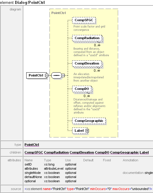
Note the attributes of the element. The first attribute, setID, allows us to set an ID to the control. The ID is particularly important if more than one control of the same type is placed on a dialog, as we would need to positively identify which control we want to retrieve data from.
The next attribute is one that is already familiar to us. The attributes attribute will be set to "core" here, as it was in the previous tutorial.
The next attribute, singleMode would be set to true if we only wanted the user to select one point and one point only. However, we don't want that restriction in this case. In this application the user should be allowed to select as many points as desired.
The next attribute, defaultNone is used to determine what to return if no values are entered into the control. If it is set to true, then if no value is entered, then no data will be returned, i.e. the user selected no points, so no point data is returned. However, sometimes the user may be interested in returning all points by default. If defaultNone is set to false, then if no value is entered, ALL data is returned.
The final attribute, optional, is used to determine if the user must enter some value in the control or not. If optional is true, and no value is entered, the user may proceed and leave the dialog via the OK button, however if optional is false all the user can do is Cancel unless a value is entered.
Note also, that the PointCtrl element has a child element called Label that allows the user to add a textual label to the control, in a similar way to the way we can add a title to a Dialog control.
Note also, that the PointCtrl element, like the Operation element also has a child element CompSFGC, allowing the computation of scale factors and grid convergences for the points selected from this control. In other words, we are replacing the Operation element of the previous tutorial, which returned all Points for us, with the PointCtrl element, which returns the points we choose.
Return to the XSL editor, and add the following code block inside the Dialog element.
        <PointCtrl setID="1" attributes="core">
        <Label>
            <Text value="Points:"/>
        </Label>
        <CompSFGC/>
        </PointCtrl>
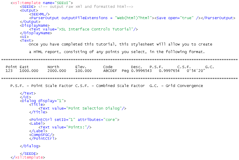
The edited style sheet thus looks like...
- Controlling What Files Are Created
Also, we don't really need to output the LISCADXML file. We are only interested in getting a report of Points in HTML. LISCAD will still extract data in XML format, but this is stored in memory, not to disk. It is from this that the style sheet takes its data for reformatting. To do this, remove the <SEEXML/> element from the <Output> element group.
Make the changes to the style sheet and save the file.
- Naming a Style Sheet
Another element that has not been mentioned previously is the <Displayname>.

The <Displayname> has a Text attribute. This text is the name that appears on the LISCAD menu once a style sheet has been installed.
- Using the Dialog to Select the Points You Want to Report
On
In LISCAD, use File/Open to open the "LISCADXML Tutorial.see" file.
Select Tasks/Utilities, then Reports/XSL Interface Controls Tutorial. If this option is not available in the Reports Menu, use the Add/Remove function to add it to the list.

And there we have our new dialog!
Select some points in the database, by accepting with the mouse.

Click OK.
Enter the following into the prompts. Note that we are not asking to save the LISCADXML file now.
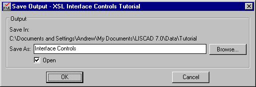
Click OK.
We have a report on only those points we selected.
- Adding Explanatory Notes to the Dialog Box
You will notice that the Point Selection Dialog we have created has 3 buttons on it which we did not define. Dialog boxes you define will always have at least these 3 buttons, OK so that you can continue, Cancel to allow you stop the process and a Notes button. In this case the Notes button is disabled as we have not written any notes for this dialog.
In a similar fashion to how we defined some notes in the tutorial XSL Style Sheets - An Introduction that relate to the style sheet in general, we can associate notes with each individual dialog box to give the end user more assistance with each step of the user interface.
Enter the following notes between the </Title> and the <PointCtrl....> elements:
            <Title>
                <Text value="Point Selection Dialog"/>
            </Title>

            <UI>
                <Text>
          Select any points you want to report on.

          You may select points by:
              Snapping and accepting points in the plan window;
              Typing individual point identifiers;
              Entering ranges of points by separating them by two dots (..)

          Multiple selections can be made by separating them with a space

          Eg.  PT4 15..20 A 5

          The order of selection is not important as the style sheet performs an
          alpha sort on the points.
          The above example would appear in the following order:

          15, 16, 17, 18, 19, 20, 5, A, PT4
                </Text>
            </UI>

            <PointCtrl setID="1" attributes="core">
Save the style sheet and run the report again.
This time the Notes button should be active. Press the Notes button and the Notes dialog will appear.
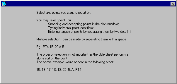
This tutorial has provided a look at how the user can create custom dialogs in LISCAD using XSL Style sheets. We have learnt how to get selected Points out of a SEE database and how to give the end user assistance with using your style sheet.
This is a useful tool to select certain points. However sometimes we may want to select many points or entities that say belong to the same group, or lines that are less than a certain length perhaps.
In the next tutorial "XSL Style Sheets - Interface Filter Controls" we will continue to look at the dialog interface and introduce the filter control which allows the user to select entities which exhibit certain behaviours.
Conclusion
You have now completed the Tutorial on the XSL Style Sheets - Interface Controls and should have a good understanding of the following:
- Creating a custom dialog screen to extract certain elements from LISCAD to XML;
- Point selection Controls;
- Adding specific user notes to a custom dialog;
- The LISCAD-SEEDE-1.0 Schema documentation;
- Familiarization with the <Dialog> <PointCtrl> and <SEEDE> elements.