To complete this tutorial you will require the Profiles & Design module.
Note: This tutorial cannot be completed using LISCAD Lite.
Aim
The aim of this tutorial is to create a Template Implementation Set which will control how template instructions are applied to create a set of design cross sections for a Bypass Road Construction.
Before you begin
Select this button to install the required data files.
- Data Set Review
Before creating a Template Implementation Set and Applying the design we will just take a few moments to review the data set we will be working with.
Select File/Open and open the file called "Template Implementation.see".
Select Window/Section Manager to view the alignments and sections currently in the data set.
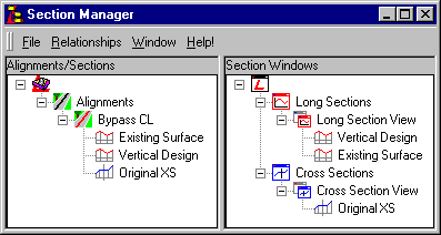
This data set contains a horizontal design control alignment named "Bypass CL".
Along this horizontal alignment we have created a long section of the current natural surface named "Existing Surface". Using the "Existing Surface" long section as a guide, a vertical design has been created called "Vertical Design". To view these long sections either right click on Long Section View in the Section Manager to bring up the pop-up menu and select Open, or select Window/Long Section View from the main LISCAD menu. To review how to create Long Sections, refer to the tutorial "Creating Long Sections".
The long section "Vertical Design" will be used by the Template Implementation Set to provide the vertical control for our design templates. As "Vertical Design" is along the horizontal alignment "Bypass CL" we also have horizontal control. To review how to create a vertical design, refer to the tutorial "Creating a Vertical Road Design".
Along this horizontal alignment we have also created a set of cross sections of the current natural surface named "Original XS". These cross sections have been created by placing Section Markers every 20m along "Bypass CL" as well as at horizontal and vertical tangent points. A corridor of interest was established 30m either side of the alignment for its full length enabling 60m wide cross sections to be created. To view the cross sections either right click on Cross Section View in the Section Manager to bring up the pop-up menu and select Open, or select Window/Cross Section View from the main LISCAD menu. You can then step through the cross sections using the View buttons on the toolbar. To review how to create a Cross Section Set, refer to the tutorial "Creating Cross Sections".
- Template Design Review
We will now have a look at the template that will be used for this design. From any of the views select Task/Utilities/Tables/Template Editor. From the Template Editor menu select File/Open and open "Template 2.tle". This generic template will be used to design the final road surface whether it is in a cut or fill situation. It refers to the Intersecting Surface "EXISTSURF" which we will have to match up with a real surface object in our data set. To review how to create a template, refer to the tutorial "Using the Template Editor".
Close the Template Editor without making any changes to the template.
- Open the Template Implementation Set Editor
We will now create a Template Implementation Set to bring everything together. The Template Implementation Set sets up the controls to be able to tell the system how to apply templates to the existing data set, with respect to existing Alignments, Long Sections and Cross Section Sets to form a new set of design cross sections.
Note: Unlike the Templates, which are generic and can be used by any Template Implementation Set, the Template Implementation Set is specific to the current data set and is stored inside the *.see data base.
From the Plan View window select Task/Profiles & Design and then Profile/Template Implementation to open up the Template Implementation Set Editor.

The Template Implementation Set Editor is the controlling dialog for setting up all the parameters required to apply templates to the primary control alignment to produce a set of design cross sections.
- Establish the Template Control
As this is a new Template Implementation Set the Implementation Set field will be blank and most of the buttons on this dialog will be disabled. This will remain so until the Control Parameters have been established.
Select the Control Parameters button to Open the Control Parameters dialog box to set the vertical control, the template library and the code table to use.
Under Vertical Control select the Long Section radio button as we want the design templates to be controlled by a long section. Select the Long Section "Vertical Design" from the drop list.
Enter the folder and file name of the template library that you wish to use. The browse button can be used to search for template library files. Select "Template 2.tle". The template library files would normally be found in your User folder. By default the User folder is set to your Common Application Data Folder. If you are having problems finding your User folder go to Utilities/Configure/Folders to see where it is set to. Note: You will have to close the current data file to be able to access the Configure/Folders menu.
Select the code table "Tutorials" - which is to be used when assigning attributes to points in the design. Select OK. This will check whether the selected template library folder and name is valid. If so, the control parameters are accepted and it returns to the main Template Implementation Set Editor dialog box

Now that you have established your control the Template Implementation Set Editor will now be fully activated.
- Save the Template Implementation Set
Before setting up all the other parameters we will give the Implementation Set a name and save the control.
The Open Cross Section in option selects which cross section window the new design cross section set should be opened in after creation. From drop down list select "Cross Section View". This will open up our design after we apply it in the same cross section view as our "Original XS" cross section set. This way we will be able to immediately see how our design relates to the existing surface.
Next enter the name to be given to the resultant design cross section set when the templates are applied i.e. Cross Section Set Name - "Final Design Surface".
Select the Save button. This dialog is used to save a new Template Implementation Set or to make a copy of an existing one.
Please enter the name "Final Surface IS" and accept the OK button.

- Attach the Templates
Next select the Attach Templates button. The Attach Templates dialog allows templates to be attached to the left and right side of the control at any given distance or chainage. Enter a start chainage of "0.000". The Left / Right Template drop down lists show all the templates in the template library. For both the Left and Right select the template "Bypass Road Design". Now press Add to enter it into the table. We only need to attach the template at the start of the control as templates remain attached along the length of the control until they are changed.
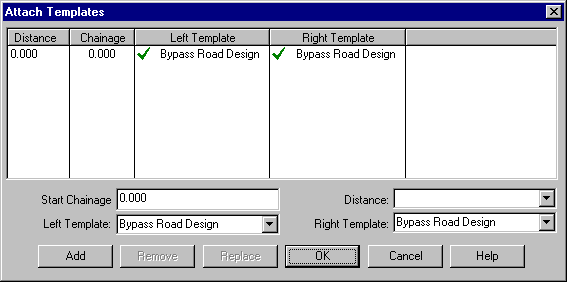
Press OK, to close the dialog box and return to the main Template Implementation Set Editor dialog box.
- Match the Intersecting Surfaces
Press the Match Intersecting Surfaces button on the Template Implementation Set Editor.
This enables the generic surface names used in the template file to be matched up with real surfaces in the data set. The Template Intersection Objects as used by the templates in the template library are listed here. As all our tests only relate to one surface "EXISTSURF" is the only generic surface name listed. Click on "EXISTSURF" to highlight it and then set the Surface Type to "Cross Section Set". This will list all the available cross section sets in the data set attached to our control alignment "Bypass CL". As there is only one cross section set "Original XS" it will be selected automatically.
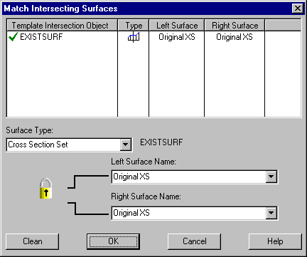
Select OK to save the current surface matches, close the dialog box and return to the main Template Implementation Set Editor dialog box.
- Enter Template Modifications
Now press the Modifications button on the Template Implementation Set Editor.
The Modifications dialog enables the templates that have been attached to the control to be modified to suit the local conditions. This is achieved by modifying combinations of offsets, elevations and grades at selected points on the template. This is useful for applying such things as super-elevation and road widening.
The Label drop down list contains the labels of the currently attached templates. In our template the label "SUPER" was designated to control the superelevation and road widening. Select the label "SUPER". This is the template point that we wish to modify.
In the Start Chainage field type in a chainage of "0.000" and use the Tab key to access the next available field. In the End Chainage field type in "100.000". This signifies that we want the modification to start taking effect at chainage 0.000 and be fully implemented by the time we reach chainage 100.000.
Before entering anymore data please make sure that the Grade & Offset radio button is checked. Selecting this radio button will enable the Grade & Offset edit fields, allowing us to enter the required modifications.
Enter an Offset of "0.000". In the Grade (%) field enter a change in grade of "2.5" percent.
The Apply to field enables the user to select one of the following:-
<-- to apply the changes to templates attached to the left of the control line;
--> to apply the changes to templates attached to the right of the control line;
<--> to apply the changes to templates attached to either side of the control line.
In this case choose "<--" as we want to apply the changes to templates attached to the left of the control line.
Next, select the Continue check box as we want the modifications to be maintained once the end distance has been reached. In the Comment field enter "Raise road up to level".
Select the Insert button to insert the new instruction into the table.
Continue to Insert the following modifications. Note that first the modification instructions to the left template are entered followed by the right template.
Note: The order of applying modifications is important as more than one modification can be applied at the same point at any given time. In such a case the first modification is applied and then the next modification is applied to the previously modified point etc.
It is not necessary to enter all the left modifications followed by the right modifications, it just makes it easier to read.
Use the table below to Insert all the Template Modifications and select OK when completed.
Note: If a row is selected in the Template Modifications table the new instruction will be inserted below the selected row. To change the order of the rows use the arrows on the left of the dialog to move the selected modification up or down
Label Start Ch End Ch Offset Grade Template Continue Comment SUPER 0 100 0 2.5% <- Yes Raise road until it is level SUPER 100 158 1 4% <- Yes Widen road by 1m and increase grade by 4% SUPER 292 398 0 -4% <- Yes Maintain new road width and bring it back to level SUPER 398 481 0 -4% <- Yes Maintain new road width and decrease grade by 4% SUPER 561 661 -1 1% <- Yes Return to original road width and raise road by 1% SUPER 661 861 0 0.5% <- Yes Return road to original grade of -2.5% SUPER 100 158 1 -1.5% -> Yes Widen road by 1m drop road to -4% SUPER 292 398 0 4% -> Yes Maintain new road width and raise road to level SUPER 398 481 0 4% -> Yes Maintain new road width and raise road to 4% SUPER 561 661 -1 -4% -> Yes Return to original road width and bring back down to level SUPER 661 861 0 -2.5% -> Yes Return road to original grade of -2.5% 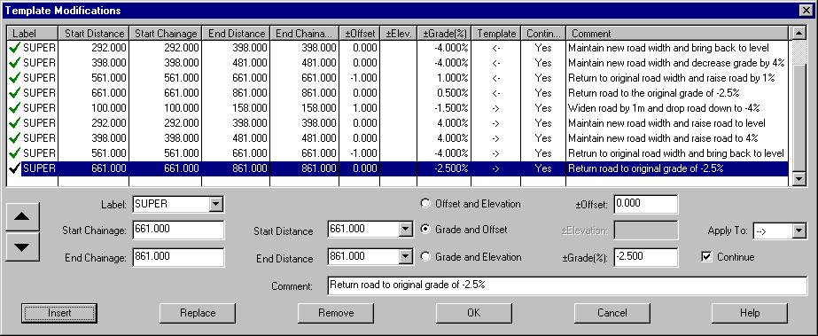
- Set the Output Parameters
Back at the main Template Implementation Set Editor dialog box select the Output Parameters Button. This enables the parameters to be set up that control the extent of the design, how the design should integrate with existing cross section sets and what its appearance should look like.

Please make the required alterations in the dialog box as displayed.
The Output Type drop down list gives 4 options of how the template can be applied. We will be using "Design Only". This option will create a design cross section set from the attached templates at every section marker along the alignment that lies between the start and end chainage / distance values entered.
The three remaining options are:
- Add Design to Existing by Range
- Replace Existing with Design
- Add Design to Existing in Total
These selections all merge the design into existing cross section sets to form single combined cross section sets.
Please consult the Help system for a detailed explanation of these Output types.
Select OK to accept the current settings, which closes the dialog box and returns to the main Template Implementation Set Editor dialog box.
- Apply the Template Implementation Set
The Implementation of the Template is now complete and it is time to apply the "Final Surface IS" to create the "Final Design Surface" cross section set.
Select the Apply Template Implementation Set button which applies the templates at every section marker between the Design Range and creates a new design cross section set and opens it in the cross section window currently displaying the "Original XS".
- Define End Areas
Now select Display/Features and select "Final Design Surface" from the droop down list. Turn on the Section Name Line Attribute and the Template Locations. Select OK when finished.
Now to display the End Areas select Volume/Define End Areas. Select Define End Areas By: Two Surfaces, From Surface: "Original XS" and To Surface: "Final Design Surface" and press OK.
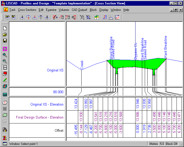
You can now step through the sections to see how the design has integrated into the existing surface. Apart from the first section (23.775), which shows the road surface and shoulder without any drains or batters due to a lack of original field data to match up with, all design sections match neatly to the existing surface.
Note: The cross sections in this view have a vertical exaggeration of x5 applied to the display to make the surface interaction more pronounced.
Conclusion
You have now completed this tutorial and should have a good understanding of how to implement a template to create a set of design cross sections.
You have also learnt how to:
- To set the vertical control, the template library and the code table to use.
- Determine which templates to attach at which locations along the control.
- Enable the generic surface names in the template library to be matched with real surfaces in the current data set.
- Enable changes to be made to the templates as they are applied. i.e. super-elevation
- Set the chainages that the design cross sections are to be generated for.
- Set how the design cross sections are to be applied with respect to existing cross sections.
- Set the colour and line style to apply to the design surface.