To complete this tutorial you will require the Profiles & Design module.
Note: This tutorial cannot be completed using LISCAD Lite.
Aim
The aim of this tutorial is to show you how to create cross sections.
Typical Scenario
You have a project that requires a set of cross sections to be created along the proposed centre line of a road.
Before you begin
Select this button to obtain the required data file.
- Set the Section Marker Display and Attributes
Then select File/Open and open "Cross Sections.see" in the Tutorial folder.
First select Display/Features/Alignments tab and ensure the following settings have been made to display the attributes of the road centre line alignment.
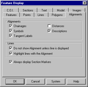
Select OK to apply the display settings.
Cross sections are created along primary alignments at intervals defined by section markers. As we already have a primary alignment called "Design", section markers now need to be created. To do this select Task/Profiles & Design.
Then select Attributes/Section Markers and set the attributes as shown here.
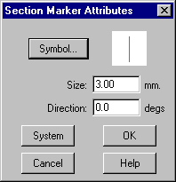
Press OK to save these settings.
- Create the Section Markers Along the Alignment
Select Create/Section Markers, then Method/by Range.
In the Create Section Markers by Range dialog make the settings as shown here.
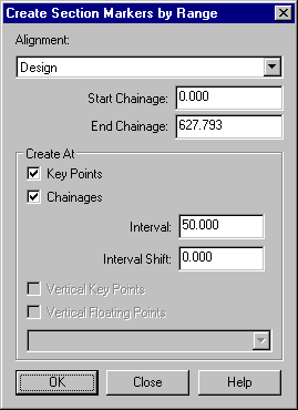
Press OK to create a series of section markers along the alignment at the displayed chainages and key points.
Close the dialog.
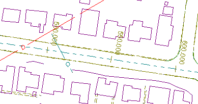
The section markers you created will look something like this.
- Create a Corridor of Interest
You now need to create a corridor of interest to define the extents of the cross sections along the entire length of the centre line alignment.
To do this select Create/Corridor of Interest then Method/Table.
In the Corridor of Interest Table dialog select "Design" from the Alignment list.
Snap and accept the point at chainage 0.000.
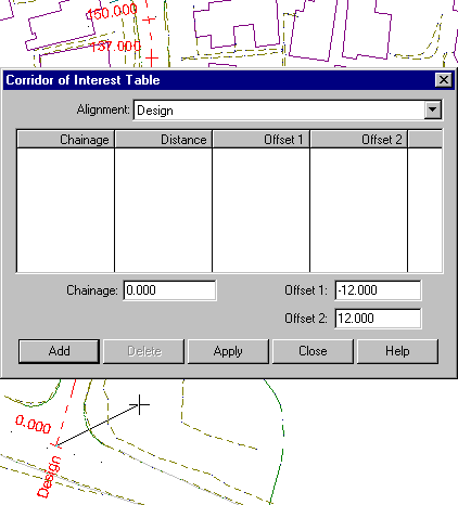
Key -12.000 into the Offset 1: field and 12.000 into the Offset 2: field, and press Add. The chainage and offset values are transferred to the table display.
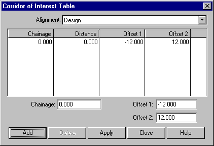
Snap and accept the point at chainage 94.875.
Key -14.000 into the Offset 1: field and 14.000 into the Offset 2: field, and press Add. The chainage and offset values are transferred to the table display.
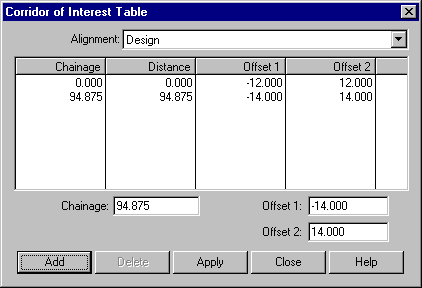
Repeat the previous steps to enter two more chainage points using the values shown in the table below.
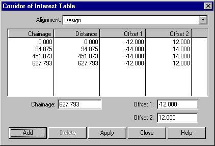
Press Apply to create the corridor of interest and then Close to close the dialog.
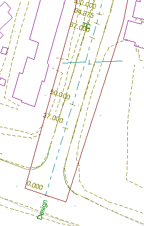
The corridor of interest is displayed as a continuous line that surrounds the centre line alignment.
- Create a Cross Section Set from the Digital Terrain Model
The cross section set is now ready to be created.
Select Profile/Cross Section/Create. Press the Parameters button to show the Cross Section Parameters dialog.
Make the settings as shown below which will ensure that Model 1 in "Cross Sections.see" is used for the cross section set extraction.
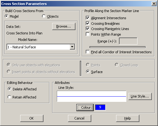
Select OK to save the settings and return to the Cross Section Creation dialog.
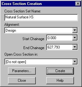
Make the settings as shown here and select Create to create the cross section set.
Select OK when the confirmation message shows.
- Create a Second Cross Section Set Representing the Underground
Utilities
You will now create another cross section set. This time showing any utilities that intersect with a cross section.
To do this first select the Parameters button to show the Cross Section Parameters dialog.
Make the settings as shown below. Then select OK.
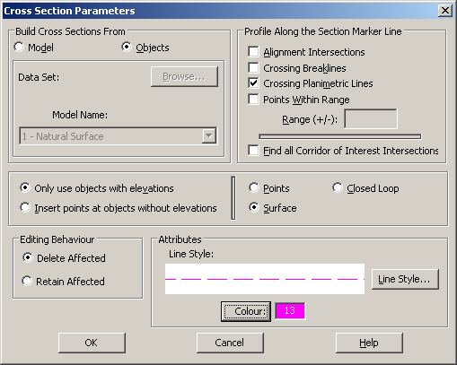
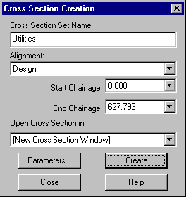
Enter the values shown here in the Cross Section Creation dialog and select Create to create the cross section set.
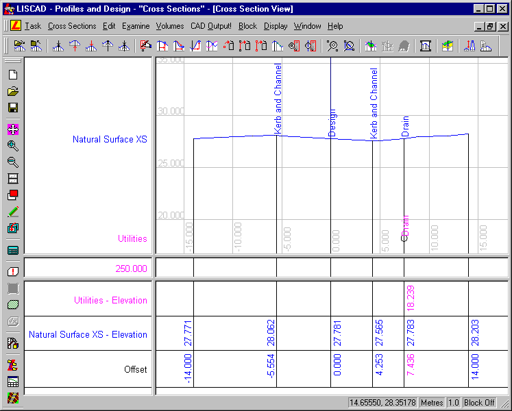
A new cross section window is created and displays the first cross section (at chainage 250) in the "Utilities" cross section set. (This is the first section that had any crossing planimetric lines. There is only one other section that met the criteria and hence there are only two cross sections in the Utilities set, which show an underground drain.)
- Display the Two Cross Section Sets
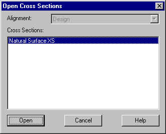
Select Cross Sections/Open.
Select the "Natural Surface XS" cross section and then Open.
Both cross sections that were created are now displayed at chainage 250.
- Set up the Cross Section Display
You will now alter the display of information for the cross sections. To do this select Display/Features.
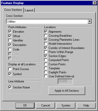
In the Feature Display dialog select the Cross Sections tab and set the following options.
Tip: You can quickly show the Display Features dialog by right clicking anywhere on the screen and selecting it from the floating menu.
Then select the Layout tab and set the following options.
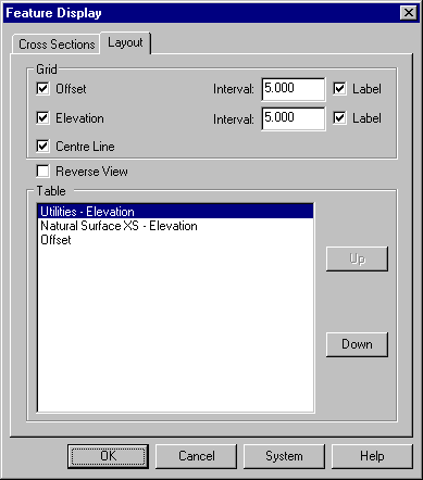
Select OK to close the dialog and apply the display options to the "Utilities" cross section.
You will notice that the changes have only been applied to the "Utilities" cross section. To apply display settings to the "Natural Surface XS" cross section.
Select Display/Features again and select the Cross Sections tab.
Select "Natural Surface XS" from the Cross Sections list and make the same settings as for the "Utilities" cross sections, except for the Symbol check box.
Press OK.
The dialog will close and the display settings will be applied to the "Natural Surface XS" cross section.
Use the Fit tool to fit the cross section to the window.
- Step through the Cross Section Set
Various commands are available to navigate through the cross sections.
Select Display/First Section to go to the first cross section in the set. In this case it is at chainage 0.000.
Then use Display/Next and Display/Previous to move through the cross section sets. Buttons for these commands are as follows.

Select Display/Go To Section and select Chainage: 250.000.
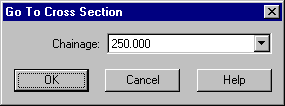
Press OK.
An extract of how this cross section should appear is shown below. This cross section shows a drainpipe intersecting with a cross section.
Conclusion
You have now completed this tutorial and should have a good understanding of how to create and view cross sections.
You have also learnt how to:
- Set Section Marker attributes.
- Create Section Markers by range
- Create a Corridor of Interest to control extent of cross sections.
- Set parameters to control the type of cross section set created.
- Create multiple sets of cross sections
- Create a cross section view.
- Open multiple cross sections in the same cross section view.
- Control the display of cross section features in the cross section view.
- View different cross sections using the various tools.