To complete this tutorial you will require the Profiles
& Design module.
Note: This tutorial cannot be completed using LISCAD Lite.
Aim
The aim of this tutorial is to create a series of sequential instructions to create a cross section design surface for the bypass road using the LISCAD Template Editor.
Before you begin
Select this button to install the required data files.
- Open the Template Editor
Select File/Open and open the file called "Template Editor.see" in the Tutorial folder.
Note: A template surface is a single path surface attached to either the left or right of a control line. If the design surface is to be symmetrical (either side of the control line) then it is not necessary to create a template that describes the entire surface. It is only necessary to design half the profile and then attach the template to both the left and right of the control.
As the Template Editor can be used to edit templates that can be used with any data sets it can be accessed whether you have a data set open or not. If you do not have a job open select Tables/Template Editor command to open the Template Editor. If you do have a job open select the Utilities Task and then select Tables/Template Editor.
From within the Template Editor select File/Open and open the file called "Template 1.tle".
The top area of the Template Editor displays a graphic representation of the currently selected template. This display will be continually updated automatically as template instructions are entered or edited.
The lower area displays a spread sheet grid, allowing the editing of the current template, and a tab control to allow the selection of different templates within that file.
- Start Building a New Template
The first instruction row is always considered to be the location of the start of the template. Instruction Row 1 establishes the starting point.
Enter the following:
Do: Always (Default) Mode:  Offset
& Elevation Difference (Default) - The Mode column
controls how offsets, elevation differences and grades are to be
entered. The Mode column shows an icon which when
pressed will step through the five available modes. The left mouse
button takes you forward through the choices the right mouse button
takes you back. With this mode only the Offset and Elevation Difference
fields will be active in this row. The grade will be computed from
the offset and elevation difference entered.
Offset
& Elevation Difference (Default) - The Mode column
controls how offsets, elevation differences and grades are to be
entered. The Mode column shows an icon which when
pressed will step through the five available modes. The left mouse
button takes you forward through the choices the right mouse button
takes you back. With this mode only the Offset and Elevation Difference
fields will be active in this row. The grade will be computed from
the offset and elevation difference entered.Offset: 0.000 (Default) - The offset is always considered to be positive away from the reference point and negative towards the reference point. Elevation: 0.000 (Default) - The elevation difference is considered to be positive up and negative down. As we want the template to start at the reference point the Offset and elevation difference are both set to 0.00. False: Store Offset & Elevation - This instruction tells the template to store the offset, elevation difference and / or grade combination entered as a point in the cross section surface. Code: ROAD - The Code column enables a code to be assigned to the point created in the template cross section. A drop down list showing the codes in the current code table can be activated by clicking on the Code field. Select ROAD from the drop down list. New codes can also be entered; they must be upper case, no more than eight characters and cannot contain spaces. New codes are not added to the code table. String (<>): 01 - The String column enables two character string identifiers to be assigned to the point created in the template cross section. They are used to create line strings between cross sections when cross sections are put back into the plan view. Comment: Connect to Long Section - allows you to optionally enter a statement about the instruction on this line. This can be valuable to assist in understanding what the instruction is attempting to achieve, especially when editing a template or coming back to one at a later time. 
To create the next instruction from the Comment field press either the Enter or Tab keys, or alternatively click on the asterisk in the instruction row column below the last instruction.
Instruction Row 2 creates the road surface. Enter the following:
Label: SUPER - The Template Editor label column serves two functions: It can be used as a label for the Go To columns or used as a label to control any modifications to the point the labelled row would create in the Template Implementation Set. This label will be used to implement the super elevation values for the road surface. The super elevation values are applied later via the Template Implementation Set Editor/Modifications dialog box. Do: Always - This means we wish to process this instruction regardless of whether the result of the previous intersection test was True or False. Mode:  Offset
& Grade - How offsets, elevation differences and grades are
entered is controlled by the Mode column. The
Mode column shows an icon which when pressed will step
through the five available modes. The left mouse button takes you
forward through the choices the right mouse button takes you back.
Only the Offset and Grade fields will be active in this row, the
elevation difference will be computed from the offset and grade
entered.
 Offset: 3.5 Grade: -2.5 - Grades are considered to be positive when rising and negative when falling. False: Store Offset & Elevation - The offset, elevation difference and grade combination entered will be used to place a point in the cross section at this location. A line will be drawn from the last point in the surface to this point. Note: If an Intersecting Surface has not been entered the intersection result is always be considered to be False. Code: ROAD - The code column enables a code to be assigned to the point created in the template cross section. A drop down list showing the codes in the current code table can be activated by clicking on the Code field. Select ROAD from the drop down list. New codes can also be entered; they must be upper case, no more than eight characters and cannot contain spaces. New codes are not added to the code table. String (<>): 02 Comment: Create road surface 
Instruction Row 3 defines the road shoulder. Enter the following:
Do: Always Mode:  Offset
& Grade
Offset
& GradeOffset: 1.5 Grade: -3.5 False: Store Offset & Elevation Code: SHOULDER String (<>): 01 Comment: Create road shoulder 
We have now created the minimum half road width of 5m (road surface + shoulder).
Instruction Row 4 determines whether the design at this point is in cut or fill. Enter the following:
Do: Always Mode:  Offset & Elevation Difference
Offset: 0.0 Elevation: 5.0 - This sends a probe straight up for 5m Intersecting Surface: EXISTSURF - This determines that tests are to be conducted between the probe line generated by the Offset & Elevation Difference fields and the EXISTSURF. EXISTSURF will be assigned to a real surface later when the design is applied to a data set.
Note: An intersecting surface can be thought of as an Alignment, a Long Section, or a Cross Section Set. At this stage arbitrary names are given to intersecting surfaces as templates can be used with any data sets.True: Nothing - Both the offset/elevation difference combination entered and the resultant intersection point with the intersecting surface will be ignored. This is commonly used as a test to determine what should be done next and can then proceed to the next row of template instructions or optionally go to another row further down the instructions. Note that the True field will only be active if a name has been entered into the corresponding Intersecting Surfaces field. Go To: CUT- If the surface intersection is found to be true then the instructions will proceed directly down to the next instruction labelled "CUT" without processing any instructions in between. False: Nothing Go To: FILL - If the surface intersection is found to be false then the instructions will proceed directly down to the next instruction labelled as "FILL" without processing any instructions in between. Test: ON - This check box allows you to view the results of a true or false intersecting surface test. Checking this box represents a true intersection. In this case it displays the CUT situation. Turning it off displays the FILL situation. This test is only available when an Intersecting Surface has been entered. Comment: Test for cut or fill 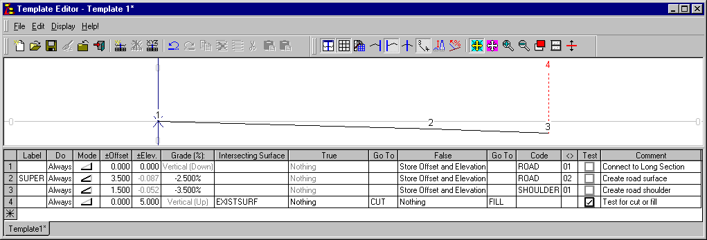
- Define the "Cut" Condition
Instruction Row 5 defines the start of the CUT situation. If the design is in CUT we will try to create a drain at the edge of the shoulder. Enter the following:
Label: CUT Do True - This instruction will now only be executed if the results of the last instruction were True.
In this case we know that the instruction has to be True to have got here in the first place, so we could just as easily have left this field as Always with the same result. However if the instructions in row 4 did not have the Go To CUT defined we could have omitted the Label CUT in this instruction and the results would have been the same. (The aim of this explanation has not been to try and confuse matters, but to illustrate that there is often more than one way to achieve the desired result.)Mode:  Offset & Elevation Difference
Offset: 0.1 Elevation: -0.3 Intersecting Surface: EXISTSURF True: Store Intersection Point - The resultant intersection point from the offset/elevation difference entered and the Intersecting Surface will be used to place a point in the cross section at this location. A line will be drawn from the last point in the surface to this point. Go To: STOP - If a Go To name is defined and not used it will cause the template to terminate as it will progress through the instructions looking for the label without success. (This Go To name could be anything that is not defined in the Label column) False: Store Offset & Elevation - The Go To field for this case should be left blank. Code: DRAIN String (<>): 01 Test: OFF Comment: Test if drain intersects the NS 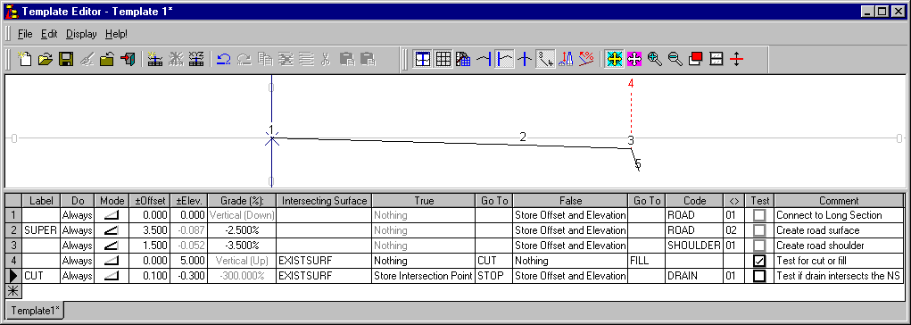
Instruction Rows 6, 7 & 8 define the remainder of the drain similarly to row 5.
Instruction Row 6 defines the drain base. Enter the following:
Do Always Mode:  Offset & Elevation Difference
Offset: 0.5 Elevation: 0.0 Intersecting Surface: EXISTSURF True: Store Intersection Point Go To: STOP False: Store Offset & Elevation Code: DRAIN String (<>): 02 Test: OFF Comment: Drain base. Test for NS intersection Instruction Row 7 defines the drain side. Enter the following:
Do Always Mode:  Offset & Elevation Difference
Offset: 0.1 Elevation: 0.3 Intersecting Surface: EXISTSURF True: Store Intersection Point Go To: STOP False: Store Offset & Elevation Code: DRAIN String (<>): 03 Test: OFF Comment: Drain side. Test for NS intersection Instruction Row 8 defines the drain runoff slope. Enter the following:
Do Always Mode:  Offset & Grade
Offset: 0.5 Grade: 5.0 Intersecting Surface: EXISTSURF True: Store Intersection Point Go To: STOP False: Store Offset & Elevation Code: RUNOFF String (<>): 01 Test: OFF Comment: Runoff slope. Test for NS intersection 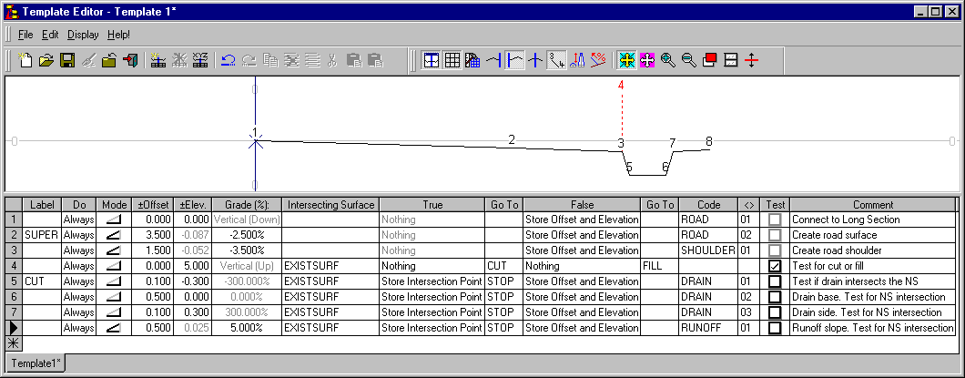
Instruction Row 9 defines the batter into the drain. If an intersection is not found it may mean that our existing survey has not been made wide enough and either the survey should be extended or a new condition will be required. Enter the following:
Do: Always Mode:  Offset & Elevation Difference
Offset: 25.0 Elevation: 5.0 Intersecting Surface: EXISTSURF True: Store Intersection Point Go To: STOP False: Nothing Go To: STOP Code: BATTER String: 01 Test: ON Comment: Create cut batter. If intersection is not found revise situation. 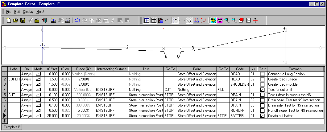
The final Line of this Template example is the FILL instruction that will be carried out if the surface intersection in instruction Line 4 was found to be false.
Before entering this information, turn the TEST OFF on Instruction Row 4 so that you can see the FILL case.
Label: FILL Do: Always Mode:  Offset & Elevation Difference
Offset: 25.0 Elevation: -5.0 Intersecting Surface: EXISTSURF True: Store Intersection Point Go To STOP False: Nothing Go To: STOP Code: BATTER String: 02 Test: ON Comment: Create fill batter 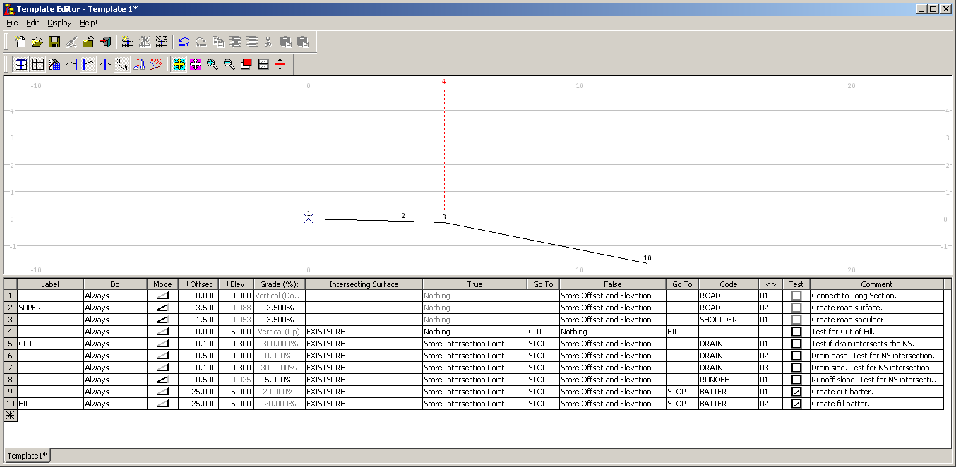
- Give the Template a Meaningful Name
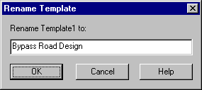
Now from the menu select Edit/Rename Template.
This will rename the active template in the currently open Template Library file.
Enter the name "Bypass Road Design" to be given to the currently active template. Template names can be up to 32 characters long. They cannot contain the following characters:- *?/\". Select OK to rename.
- Save the Template Library File
Select File/Save to save the Template Library "Template 1.tle".
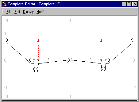
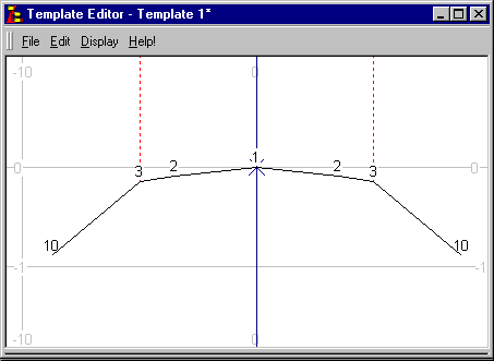
Select Display/Layout/Both to displays the template as it would appear if it was attached to both the left and right sides of the control line. Turn the TEST on Instruction Row 4 ON to view the CUT case and OFF to view the FILL case.
Conclusion
You have now completed this tutorial and should have a good understanding of how to create a template file in the LISCAD Template Editor.
You have also learnt how to:
- Display the template as it would appear if it was attached to both the left and right sides of the control line.
- Renames the active template in the currently open Template Library file