To complete this tutorial you will require the Computations Profiles & Design module.
Note: This tutorial cannot be completed using LISCAD Lite.
Aim
The aim of this tutorial is to create and implement the vertical design of a bypass road.
Before you begin
Select this button to load the required data files.
- Create the Horizontal Design Control Line
Select File/Open and open the file called "Vertical Design.see" in the Tutorial folder.
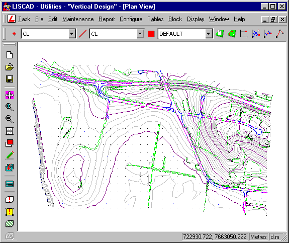
Click on Task/Computations/Attributes/Point and make sure that the Code Table is "Tutorials" and the code is "CL".
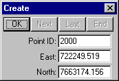
Next select Create/Point followed by Method/Coordinates. Complete the fields as shown below and select OK to create point 2000.
Select Display/Groups and turn off all groups except for the C/L group. Select Display/Features/Points and turn on Point Identifiers.
The point 2000 is the Preliminary Design Point and now we need to create the proposed centre line.
Next go to Attributes/Line and make sure that the Code Table is set to "Tutorials" and the code of the Line to be created is code "CL".
Select Create/Line and then select Method/Traversing. Complete the fields as shown below and select OK to create the centre line.
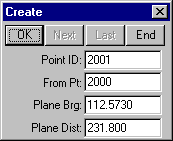
Continue creating the following points:
2001, 112°57' 30" & 231.800 (Note that direction fields are entered in ddd.mmss format.)
2002, 158°39'30" & 355.353
2003, 95°51' 05" & 576.358.
After computing the points select End to complete the centre line.
- Turn the Horizontal Control Line into an Alignment
Next turn this new line into alignment.
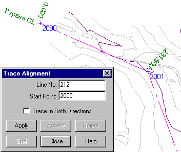
For this example the best method is via tracing through existing contiguous line objects. But first, go to Attributes/Alignment and check that the alignment name is set to "Bypass CL" and that the Start Chainage is set to 0.000.
Now select the Create/Alignment command and the Method/Trace command from the Computations task.
Select the line object just created. On snapping, the rubber band will attach to the line end point closest to the cursor position, and that point number will be placed in the start point field. The line along which the trace will commence is highlighted.
Select the Apply button and close the dialog when finished.
- Create the Transition Curves and Arcs
Select Task/Computations/Create/Combined Curve.
We need to create a new combined curve by specifying its tangent lines and various combinations of parameters. The parameters that need to be specified depend on the type of combined curve to be created and the technique chosen. The technique you choose will depend on which parameters are known.
Select the Type of combined curve as Spiral in, Arc, Spiral Out and the Technique will be Radius. Accept the Tangent Line 1 as the line between Point 2000 and 2001 and Tangent Line 2 as the line between 2001 and 2002. Set the Radius to 300 and turn on Fillet Lines.
By selecting the Fillet Lines option the tangent lines are filleted at the tangent points when the combined curve is accepted. This will cause the tangent lines to be truncated or extended as the case may be, such that they end at the tangent points. If these lines are used in an Alignment, as in this case, the alignment will be updated to pass through the combined curve.
Select Compute to Compute the combined curve and display it on the screen. All the relevant combined curve parameters (velocities, spiral lengths etc.) will be displayed in the dialog.
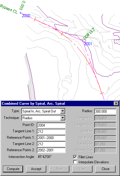
Note: When snapping and accepting the Tangent Lines the Reference Points for the tangent line segments will be automatically entered. The order that these Reference Points are filled out is dependent upon the end of the line segment the line was snapped to. The order these points appear in the edit field is not important as they are not reliant upon direction.
Select the Accept button to save the computed combined curve.
Continue the design of the horizontal geometry of the bypass centre line as displayed in the graphic below:
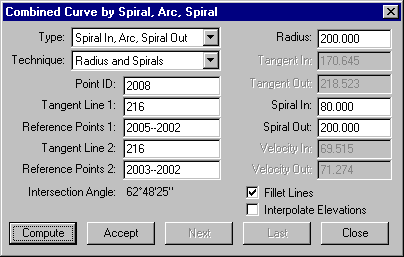
Select Compute to view the combined curve that will be created and then Accept to save it.
You have now completed the Horizontal Design of the centre line of the Bypass Road.
Before continuing select Display/Features/Points and turn off the Point Identifiers and press OK.
Now select Display/Groups and press All then OK. This will show how the design parameters entered relate to the existing features.
The next step is to create the Vertical Design of the bypass road centre line.
- Create a Long Section of the Existing Surface Along the
Design Centre Line
Before creating the vertical design it is often a good idea to create a long section of the existing terrain as this can provide a guide to your final design.
Select Task/Profiles & Design/Profile/Long Section/By Alignment.
Set the Long Section name as "Existing Surface".
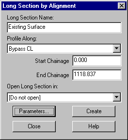
Press the Parameters button to set the Long Section creation parameters.
Make the settings as shown below which will ensure that Model 1 is used for the Long section extraction.
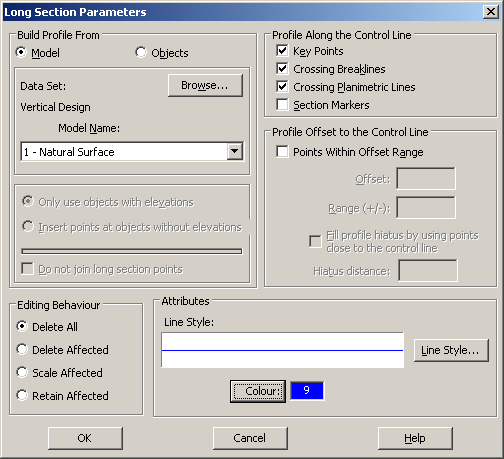
Select OK to save the settings and return to the Long Section Creation dialog.
Next select Create to create the Long Section. Select OK when the confirmation message shows.
Close down the Long Section creation dialog box.
- Create the Vertical Design Long Section
You will now create another Long section on which to base your vertical design. We need to create a long section along the full length of the Bypass CL alignment at a nominated elevation. The resulting long section will consist of two points, one at each end of the Bypass CL alignment. This type of long section is useful for providing an initial long section which will be used to commence the vertical design.
Select Task/Computations/Attributes/Point and select the code VERTCL. Alternatively select this code from the point code drop down list on the menu bar if it is installed.
Select Task/Profiles & Design/Profile/Long Section/Horizontal/by Alignment. Enter the Long Section name as "Vertical Design".
Make the settings as shown below. Then select OK.
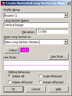
A new Long section window is created and displays the Long Section "Vertical Design".
Next select Long Sections/Open. Select the "Existing Surface" Long Section and then Open. Both Long Sections that were created are now displayed.
Place the cursor in the Long Section window and right mouse click, from the menu select Vertical Exaggeration. Set the Vertical Exaggeration to 20.0.
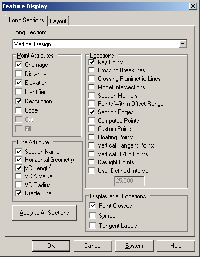
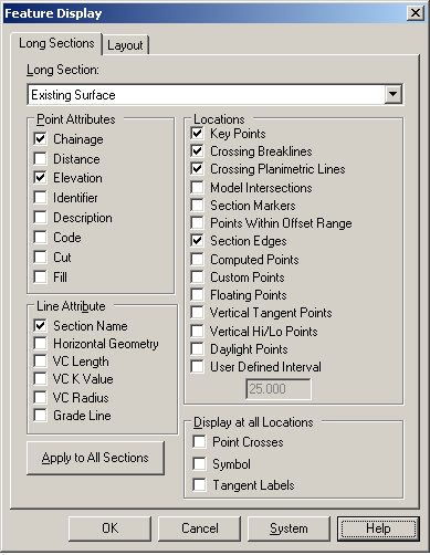
Now right click in the Long Section window again and select Display Features from the pop up menu.
For the long section "Vertical Design" set the following attributes
For the long section "Existing Surface" set the following attributes
Now select the Layout tab and turn off the Grid Chainage / Distance and Elevation.
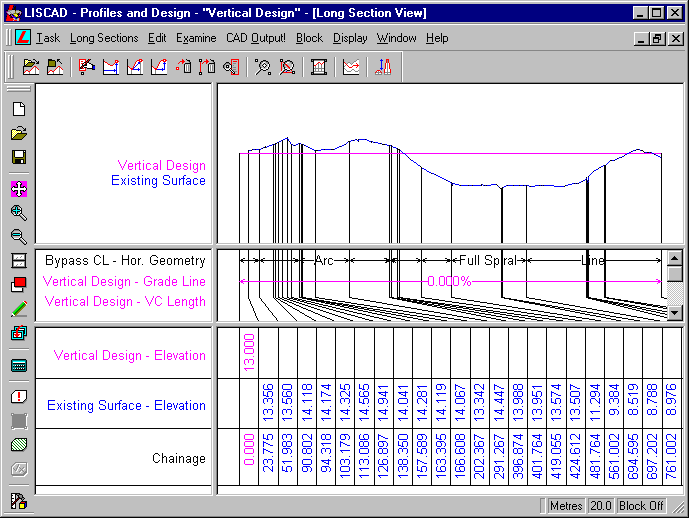
Press OK to apply the display parameters and close the dialog. Your Long Section Window should now look similar to the following:
- Anchor the Vertical Design Long Section to the Existing
Surface
Next use Display/Window (or the Window tool) to obtain a closer view of the area around Chainage 0 to Chainage 50. You will notice that the "Vertical Design" section starts at 0.000 whereas the "Existing Surface" starts at 23.775. This is because the "Vertical Design" has been created along the full length of the "Bypass CL" alignment and the "Existing Surface" has been generated from the digital terrain model and the first point in the alignment, point 2000, is outside the model. To make the vertical design meet the natural surface we will move the design to the existing surface.
Select from the menu Edit/Move Point/Absolute. Select the first point on the "Vertical Design" line (Pink Line) at Chainage 0 (Elevation 13) and then type the following values in the Move Point dialog box:
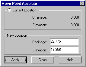
Select Apply to move the point.
The "Vertical Design" and "Existing Surface" should now commence from the same starting point. A similar process needs to be completed at the end of the Long Section. Therefore use the Display/Zoom, Fit, Pan or Window tools to obtain a closer view of the area around the end of the Long Section. This time we will use a different method. Select Edit/Move Point/Freehand. This time you will not get a dialog box but the cursor will change to the Move tool.
To be able to see the points that are in the sections so that you can be sure you are moving the correct point select Display/Features and for both sections turn on Display Point Crosses in the Display at all Locations section and press OK.
Now snap and accept the end point of the "Vertical Design", you will now find that you can move the long section point dynamically. Next snap and accept the end point of the "Existing Surface". This will move the first point selected on to the second point. To cancel out of the Move Point Freehand command you can either press the Esc key or just select the next function you want to use.
The "Vertical Design" and "Existing Surface" should now finish at the same end point chainage of 1118.837 & elevation 12.473.
- Create the Vertical Design Intersection Points
Return to Display/Features and turn off Display Point Crosses for both sections.
Next select Edit/Set Point Attributes and make the changes as displayed below.
Set the Description to VIP (Note: VIP - Vertical Intersection Point)
Set the Code to VERTIP
Turn on Custom Point
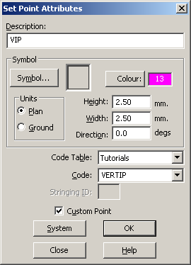
Select OK when completed
Select Edit/Create Point/By Chainage & Elevation.
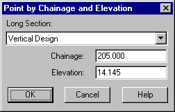
Select the "Vertical Design" long section and create the following points:
Ch. 205.000, Elev. 14.145
Ch. 690.000, Elev. 9.200
Ch. 1050.000, Elev. 13.200
Now use the menu option Edit/View Edit/Points and select the point at the first chainage on the "Vertical Design" Long Section (Pink) and change the Code of the end points to VERTCL and the Description of the first point to 23.775 and the end point to 1118.837.
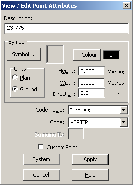
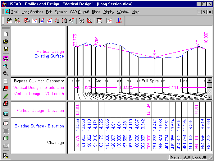
Your long section view should now look like this:
- Create the Vertical Parabolic Curves
Now we will commence the Vertical Parabola Design. Select Edit/ Vertical Curve Designer. This LISCAD feature allows Vertical Parabolic Curves to be Created, Examined, Edited and Deleted within Long Sections.
Now Select the Design Parameters button.
This dialog allows Vertical Curve Design Parameters to be entered. Velocity, reaction time, coefficient of friction and the grade of the road are used to compute a vehicle's stopping distance. Driver, object and headlight heights are used to compute the sight distances for summit and sag curves.
As the stopping distance will also vary depending upon a vehicle's mass and condition of the brakes, it is vital to design vertical curves so that the sight distance is in excess of the stopping distance, so as to provide an allowance for any unknowns.
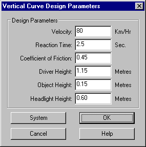
Enter the Design Parameters as displayed. Select OK when completed.
Snap to the VIP at Ch. 205.00 in the Vertical Design. Now enter the desired parabolic curve length of 300.
Note: To delete the parabola simply enter 0.00.
The horizontal length of the parabolic curve must be able to fit between the adjacent points to the vertical intersection point. If the adjacent points also have vertical curves attached, the parabolic curve being created must fit between the vertical tangent point of the adjacent curve.
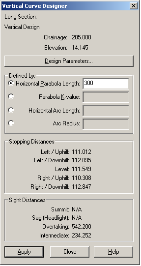
Next select the Apply button.
Notice that the Summit distance has been updated.
The sight distances are all much greater than the stopping distance making this vertical parabola satisfactory.
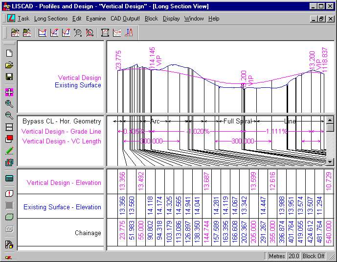
Place a vertical parabola of length 300.000 at the VIP at chainage CH 690.000.
Place a vertical parabola of length 100.000 at the VIP at chainage CH 1050.000.
Select Close when finished.
A design report for QA purposes can be created via the Task/Utilities/Report/Long Section Design command. Select the "Vertical Design" long section and press OK to view the report.
- Transfer the Vertical Long Section Design Back into the
Plan View
The final step is to transfer the Centre Line Design back into Plan, therefore select Task/Profiles & Design/Long Sections/Transfer Long Section to Plan. Select the "Vertical Design" long section and make the selections in the dialog as displayed below:
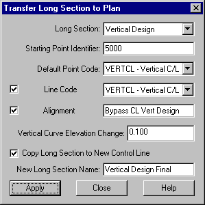
This LISCAD feature allows a long section to be transferred into the plan view of the data base by creating new points, lines and alignments as requested, with the long section elevations being applied to the points. A point will be inserted into the alignment at every 0.1 change in elevation around the vertical curves. It is also possible to copy the "Vertical Design" long section on to the new alignment created.
Select the Apply button to transfer the long section to plan and then Close to exit the dialog box.
Open the Section Manager from Window/Section Manager to view the alignments and long section that now exist in the data set. The alignment "Bypass CL" is the original horizontal design which has two long sections "Existing Surface" and "Vertical Design".
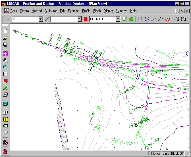
As a result of putting the "Vertical Design" back into plan a new alignment "Bypass CL Vert Design" has been created which lies over the top of "Bypass CL", but has extra points inserted into it to hold the vertical design elevations. The long section "Vertical Design" has also been copied to "Vertical Design Final" so that it is also attached to "Bypass CL Vert Design". The new alignment "Bypass CL Vert Design" has been generated on a new group VERTICAL DESIGN by virtue of the codes selected.
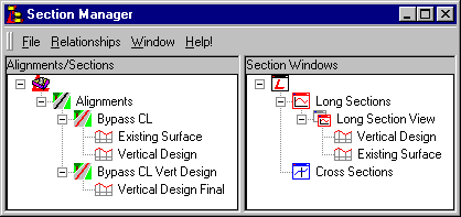
The original design alignment is copied onto a new "clean" alignment containing the design elevations. The original alignment does not get its elevations updated. This is because the original alignment may well contain its own elevations which you may not want to replace.
Select Windows/Plan View to return to the Plan view.
Select Display/Groups and Turn off (Hold down Ctrl key) the following groups: BOUNDARY, C/L, CONSTRUCTION OBJECTS & HORIZONTAL DESIGN.
Conclusion
You have now completed this tutorial and should have a good understanding of how to create a vertical design.
You have also learnt how to:
- Create a Combined Horizontal Curve.
- Create a Horizontal Long Section by Alignment.
- Adjust Display Features in the Long Section view.
- Move Points in the Long Section view.
- Use the Vertical Parabola Designer.
- Transfer Vertical Design into the Plan view