To complete this tutorial you will require the Profiles & Design module.
Note: This tutorial cannot be completed using LISCAD Lite.
The information in this tutorial builds upon the ideas and concepts presented in the tutorial "Using the Template Editor" and the tutorial "Template Implementation". Please ensure you are familiar with these before continuing.
Aim
The aim of this tutorial is to demonstrate the design of multiple surfaces. It will also show:
- Using end areas to calculate volumes;
- The use of descriptive names for intersection surfaces;
- A survey has been taken of a rural area, through which a 10m wide road pavement is to be constructed. Open storm water drains are adequate. Volumes of cut, fill and road pavement material for the design are required.
A Preamble About Surfaces
Fundamental to this tutorial is the concept, and use of surfaces in SEE. A surface is a line lying in a vertical plane. It may be either a long section or a cross section.
Surfaces can be created in a variety of ways, but SEE does not differentiate between surfaces based on the creation method, i.e. 'design', 'original ground' and 'boxing' are all considered to be just surfaces. Editing methods for 'existing' surfaces apply equally to 'design' surfaces. For example, in the tutorial "Creating Long Sections" the decision was made to create a "Pipe Line Invert" surface, to represent underground drains.
It is the designer who must decide what a surface represents, and what data it contains. When determining surfaces, it is generally best to think of them as interim surfaces that will occur during the construction process. SEE does not allow the extrusion of an area to form a volume of a particular material.
Before you begin
Select this button to install the required data files.
- Review the Example Data Set
Select File/Open... and open the data file called "Road With Boxing.see".
Select Window/Section Manager... to view the alignments, sections and implementation sets currently in the data file.
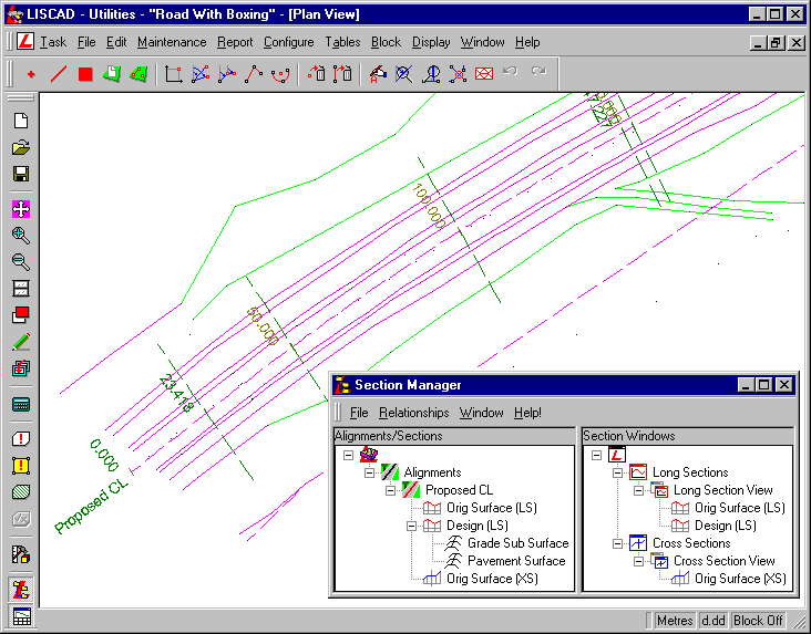
The original survey data in this file has had a design alignment called "Proposed CL" added. In addition a corridor of interest 40m wide (not shown) has been defined and a natural surface long section "Orig Surface (LS)", and cross section "Orig Surface (XS)", have been created from the TIN (model). A vertical profile long section "Design (LS)" has also been created down the centre line.
Two implementation sets have been attached to the long section "Design (LS)", called "Grade Sub Surface" and "Pavement Surface". These will be examined later.
- Review the Cross Section Design Templates
Select Task/Utilities and then Tables/Template Editor... and open "Road With Boxing.tle".
Note: There are two tabs along the bottom of the editor window, indicating that this file contains two different templates, called "Pavement Surface" and "Grade Sub Surface".
These templates use 8 codes:
- ERR - An error condition;
- CL-PAVE - The centreline of the pavement;
- EOP-PAVE - The edge of trafficable pavement for the pavement;
- CL-GDE - The centreline of the grade surface;
- EOP-GDE - The edge of the grade surface, where the drain begins;
- INV - Invert of drain;
- EOD - Outer edge of open drain;
- BATTER - Limit of works;
We will start by examining the template "Grade Sub Surface".
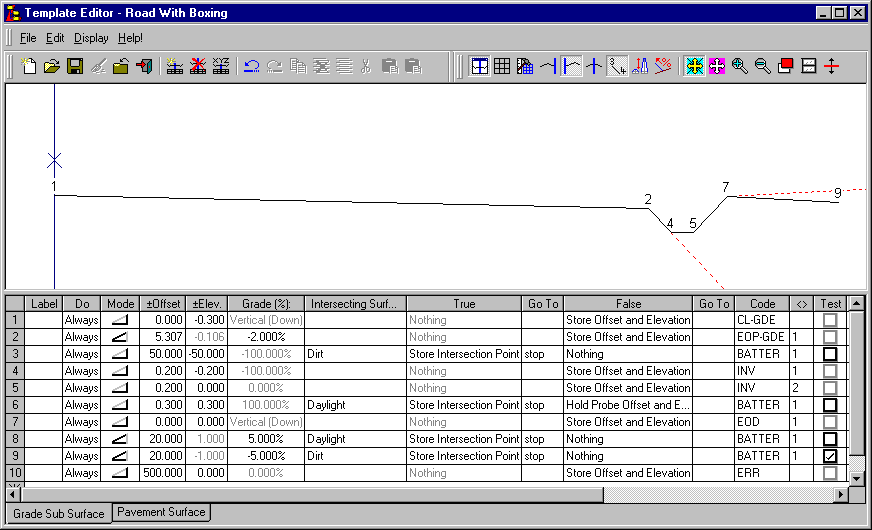
Row 1 - The template starts by creating a point 0.3m below the design/connection point. The design long section represents the finished level of the new pavement, allowing for a 300mm pavement, the grade sub surface starts 0.3m below the finished level.
Row 2 - The pavement is wider at the grade sub level than at the finished level. This is because the extra width is made up of 300mm for the 1:1 slope of the drain over the 6mm depth of the pavement, as the grade is falling at 2% over the 300mm.
Note that an extra 1mm is added, as the 6mm for the cross fall is slightly underestimated, and also because SEE uses double precision arithmetic in its calculations (i.e. accurate to a large number of decimal places). This means that you should always avoid trying to intersect with, or very close to, the end of a line.
By making the grade surface a millimetre wider, there is a clean intersection between the pavement and the grade at this level, and the pavement won't end up spilling down into the invert of the drain.
Row 3 - Check to see if we are in fill by looking down for the "Dirt". If so, create a batter point.
Row 6 - The drain is almost completed. While coming out, check to see if we hit daylight, and place a point with the appropriate code.
Select the other tab at the bottom of the editor to view the template "Pavement Surface". This template includes descriptive comments for explanation.
- Implement the Templates to Create Design Cross Sections
Close the template editor and view the implementation sets in the data file by selecting Task/Profiles & Design and then Profile/Template Implementation... (alternatively from the Section Manger, right click on one of the implementation sets and from the pop-up menu select Edit Template Implementation).
The following points are worth noting about each implementation set:
The "Grade Sub Surface" implementation set matches two different intersection objects, "Dirt" and "Daylight", to the same surface "Orig Surface (XS)". Each intersecting object can be matched to only one surface, however different intersecting objects can be matched to the same surface. This allows for the use of more descriptive names for the intersection objects.
The "Pavement Surface" implementation set has a surface "Grade" that is not currently matched. This is because it will be matched to a cross section set that is to be created by the "Grade Sub Surface" implementation set. By making implementation sets dependent on sections created by other implementations sets, hierarchies of inter related and dependent implementations sets can be created.
It can be seen in the Control Parameters dialog, that the template file "Rural Road With Boxing.tle" is being used by both implementation sets. Confirm this.
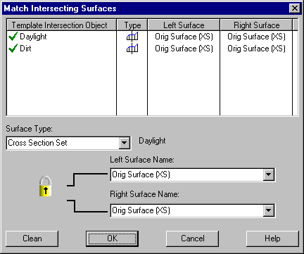
For the "Grade Sub Surface" implementation set open the Match Intersecting Surfaces dialog. Confirm that both the "Dirt" and "Daylight" intersection objects are matched to the "Original Surface (XS)".
The "Grade Sub Surface" implementation set will use the template to produce a cross section set called "Proposed SubSurf (XS)". The "Proposed SubSurf (XS)" represents the ground level, once the earthworks have taken place.
Press the Apply Template Implementation Set button to create the "Proposed SubSurf (XS)".
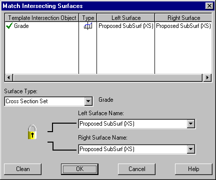
For the "Pavement Surface" implementation set open the Match Intersecting Surfaces dialog. Ensure that the "Grade" Intersection Object is matched to the "Proposed SubSurf (XS)" cross section set that you have just created.
The "Pavement Surface" implementation set creates a cross section set called "Proposed Pavement Surf (XS)" that represents the finished pavement surface.
Press the Apply Template Implementation Set button to create the "Proposed Pavement Surf (XS)".
- View the Design Cross Sections
Having applied both the implementation sets, open the resulting cross section sets in the existing Cross Section Window.
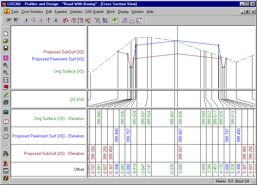
Select Display/Features from the menu. For the two new cross section sets, "Proposed SubSurf (XS)" and "Proposed Pavement Surf (XS)", check on Template locations and Section name. Step through the sections and notice the line each set follows, i.e. the shape of each surface.
Please note that a vertical exaggeration of 5 has been applied for clarification of the surfaces.
An error has occurred at chainage 1800.000 in the "Proposed SubSurf (XS)" cross section set.
There are three ways of identifying this error:
- Go to chainage 1800.000 and you will notice that the cross section extends too far out to the right.
- Select Display/Features from the menu, and turn on Codes for the cross section set and you will notice a code ERR has also been placed on the point where the error has occurred when the template was applied.
- Open the Plan View and look at the cross sections lines, notice that an error occurred to the right at the end of the alignment.
This error was caused by a lack of survey data. As this will introduce errors into the volume computations, this problem may be dealt with in a number of ways, for example:
- The best solution is to collect additional survey data; or
- From the Plan View, select Task/Computations and then Edit/Delete/Section Markers... to delete the section marker at chainage 1800.000. This method will delete the data at this chainage from all three cross section sets; or
- Open only the "Proposed SubSurf (XS)" cross section set into a new cross section view. Go to chainage 1800.000, select Block/All and then Edit/Delete/Point, 'accept' to the screen and select 'yes' when prompted to delete the section. This method will delete the data at this chainage from only this cross section set.
For the sake of this tutorial choose method 2.
- Compute the Material Volumes
The three earthworks quantities to be considered here are:
- Cut of existing material;
- Low quality, sub base material;
- Road base material;
These quantities will be calculated using the end areas method, from the cross sections created previously.
See the tutorial "Defining End Area Volumes" about setting up, and using end areas.
Select Volumes/Define End Areas... to display the dialog. The end areas to consider will be defined by Two Surfaces using only the Apply square cut at section end rule.
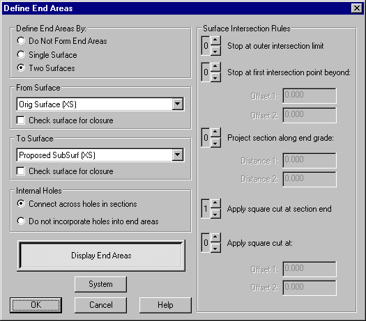
The volumes will need to be calculated twice. For the first time set the 'From Surface' to "Orig Surface (XS)", and the 'To Surface' to "Proposed SubSurf (XS)". Display the end areas, and examine the shaded area of a number of the cross sections.
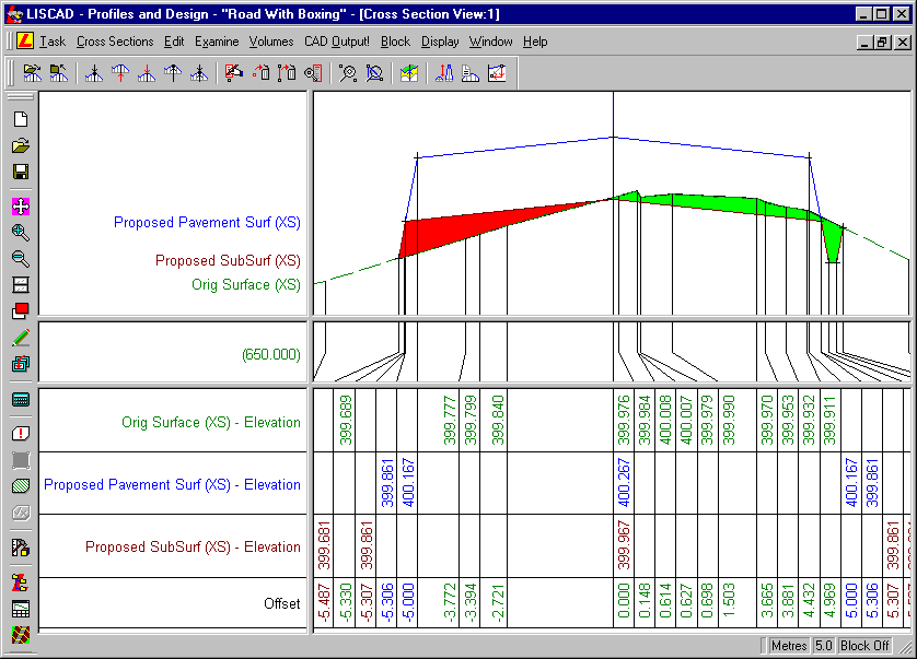
Select Volumes/Volumes by End Areas... to calculate the aggregate cut and fill volumes. The aggregate cuts are the volumes of cut of existing material. The aggregate fills are the volumes of the low quality, sub base.
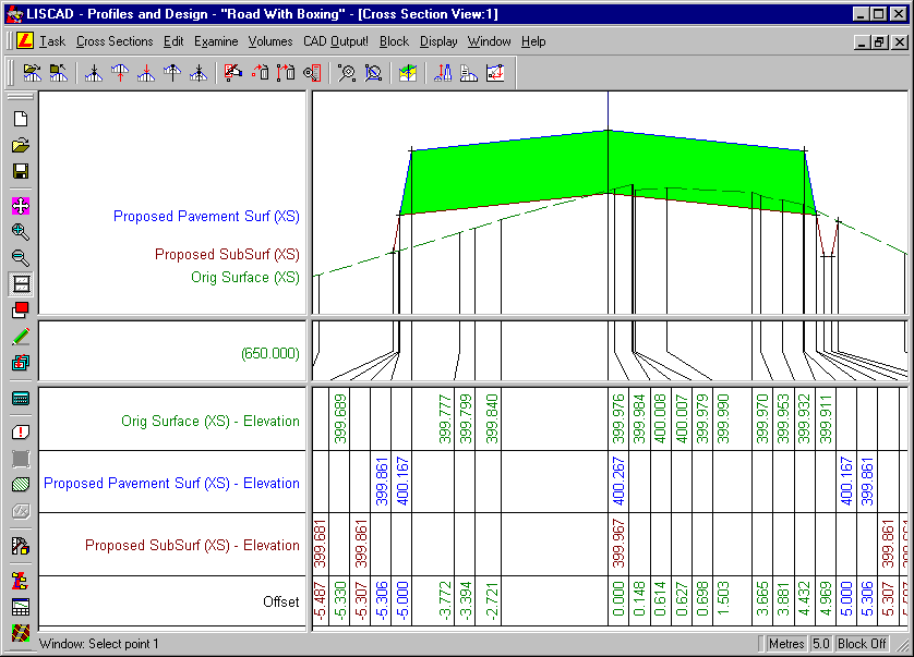
In the End Areas dialog, change the 'From Surface' to "Proposed Pavement Surf (XS)". Again, examine the shaded areas and recalculate the volumes. The volume calculated is the volume of road base material. Note that no fill is calculated as the volume is fully cut.
Further Investigation:
In row 2 of the "Grade Sub Surface" template, change the pavement width from 5.307m to 5.036m. Reapply the "Grade" and "Pavement" implementation sets. Observe the resulting shape of the cross sections created.
Conclusion
You have now completed this tutorial and should have an understanding of creating and using multiple surfaces in templates.
You should also be familiar with:
- The use of descriptive intersection object names;
- The importance of designing templates with clean intersections;