To complete this tutorial you will require the Profiles & Design module.
Note: This tutorial cannot be completed using LISCAD Lite.
The information in this tutorial builds upon the ideas and concepts presented in the tutorials "Using the Template Editor", "Template Implementation" and "Pavement Rehabilitation Design". Please ensure you are familiar with these before continuing.
Aim
The aim of this tutorial is to demonstrate template modifications in the template implementation set. It will also show:
- Checking templates apply correctly;
- Reshaping a cross section, depending upon chainage;
- Performing a template test, with respect to chainage.
An existing road has been surveyed. Design a finished surface with two 3.5m wide carriageways. Include indented parking bays and a non continuous footpath along an independent line.
Before you begin
Select this button to install the required data files.
- Review the Horizontal and Vertical Design
Select File/Open and open the data file "Local Street.see".
Select Window/Section Manager to view the alignments and sections currently in the data file.
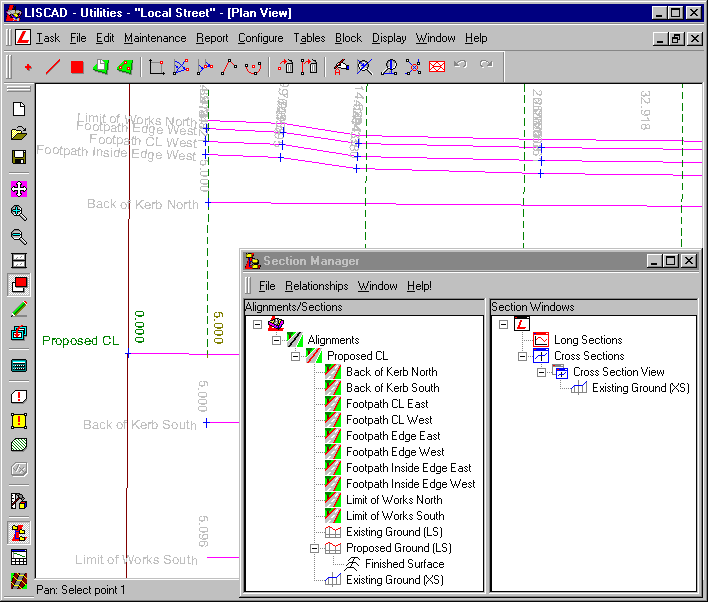
The alignments:
- Following the original survey, a design primary alignment called "Proposed CL" was created.
- Long and cross sections of the natural surface, called "Existing Ground (LS)" and "Existing Ground (XS)" respectively, were created from the primary alignment.
- A design long section, "Proposed Ground (LS)" was created based on the "Existing Ground (LS)" long section.
- A template implementation set, "Finished Surface", has been created on the design long section.
- Additional secondary alignments were also created. These are proposed lines for the footpaths, kerbs and limit of works. Note that in this tutorial only the primary alignment and the limit of works alignments will be used. The others are provided to show the line of the design. Open the Display/Groups dialog and note that the "PROP" prefix is used for groups that the points and lines of these alignments lie on. A prefix of "DES" will be used for the code of points and lines to be created by the template.
Corridor of interest and section markers:
- A 40m wide corridor of interest is attached to the primary alignment.
- Section markers have been created along the primary alignment, "Proposed CL", at a 10m spacing, with a 5m interval shift. Additional section markers have been added where the proposed pavement or footpath changes, to provide extra cross sections in these areas.
The road section to the south:
- The road section to the south (bottom of the screen) is to be a straight 3.5m wide carriageway with a 2.5% crossfall.
- This is edged with a 600mm wide barrier, or "unforgiving" kerb and channel.
- The surface then batters at a constant grade to the existing ground level at the "Limit of Works South" alignment.
The road section to the north:
- To the north, however, the situation is a more complex. The carriageway is 8.4m wide with a 2.5% crossfall.
- Again this is edged by a 600mm wide barrier kerb and channel.
- From this line, "Back of Kerb North", at 9m off the design line, the surface again batters to the existing ground level at the "Limit of Works North" alignment, which is at a variable offset.
- On this batter there is a 1.5m wide footpath.
- This footpath runs from the start of the design to chainage 107.844 and from chainage 174.105 to the end.
- The footpath has a crossfall towards the carriageway of 26mm, and the elevation at its centre is the elevation of the batter.
- Between chainages 98.754 and 125.267 and chainages 216.633 and 232.272, there are two road narrowings, or parking protectors, to restrict the carriageway to a 3.5m width.
- At the narrowings the kerb changes from the barrier profile, to a semi-mountable or "forgiving" shape.
- Also at the narrowings, the surface continues to fall, from the back of kerb to match the shape of the wider pavement.
- Review the Design Templates
It can be seen in the Control Parameters section of the Implementation Set, that the template file "Local Street.tle" is being used.
Open this file in the Template Editor.
Note there are two tabs along the bottom of the editor window, indicating that this file contains two different templates, called "Road Pavement" and "Parking bay and footpath".
These templates use 11 codes:
- ERR - An error occurred
- DES_CL - The design centre of pavement
- DES_LIP - The design edge of pavement/lip of kerb
- DES_INV - The design channel invert
- DES_FOK - The design face of kerb
- DES_BOK - The design back of kerb
- DES_NS - The design nature strip
- DES_LOW - The design limit of works
- DES_F_I - The design inside edge of footpath
- DES_F_CL - The design centreline of footpath
- DES_F_O - The design outside edge of footpath
We will start by examining the template "Road Pavement".
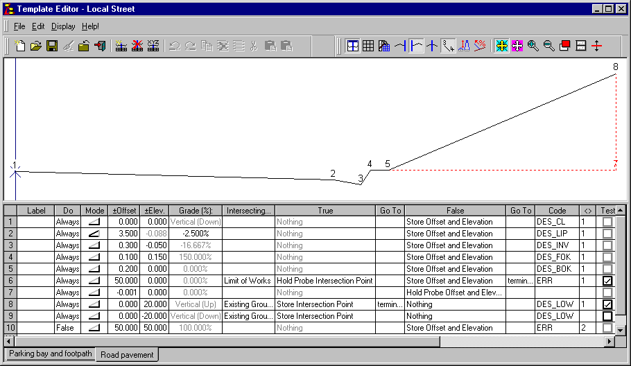
Rows 3, 4 and 5 define the barrier kerb to be used.
Row 7 brings the probe in 1mm from the limit of works alignment. This is done because the model, and hence the "Existing Ground (XS)" cross section set does not necessarily extend beyond the limit of works alignment. The probe is brought back the 1mm to ensure it has a clean intersection with the cross section set. See tutorial "Rural Road with Boxing Design" where the importance of clean intersections is also discussed.
The "Limit of Works" intersecting surface is the line of the edge of works, and is represented in the data file by the secondary alignments "Limit of Works South" and "Limit of Works North".
The "Existing Ground" is the natural or original surface. This is represented in the data file by the "Existing Ground (XS)" cross section set.
The other template in the file is called "Parking bay and footpath".
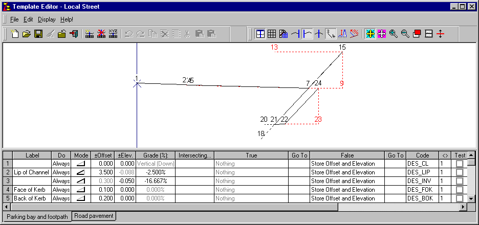
Rows 1 and 2 create a 3.5m wide pavement, with a 2.5% crossfall.
Rows 3 to 5 create the kerb and channel unit. Note that the kerb is flat. It has been given no elevation here as the elevation for the kerb face will be added by the modifications when the template is applied.

Rows 6 and 7 test to see if we are at a narrowing of the road. If we are, follow the shape dictated by the road out to a low point, at 9m off the design centre line.
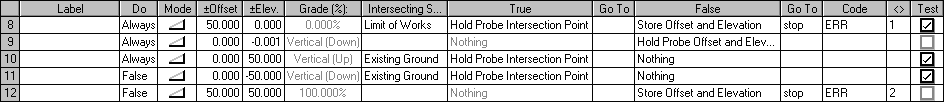
Rows 8 to 12 probe out to the edge of works, and find where the batter will finish. Please note row 9 is added to ensure a clean intersection.

By processing the template so far, the current position should be at least 9m from the design centre line. The test on row 13 should therefore always fail. However, it has a label, and a modification can be applied to control the template behaviour with respect to chainage.

Rows 15 to 17 create an inside edge of footpath point on the design centre line.

Rows 18 and 19 move the footpath edge point, off, and then back onto, the design centre line. Tutorial "Road Rehabilitation Design" describes why this is done.

The footpath edge is now at the line and level for the centre of footpath. Rows 20 to 22 create points for the footpath centre, and both edges.

These rows are similar to rows 8 to11, in that they look for the edge of works, and complete the batter. Note that no attempt is made to ensure a clean intersection with the existing ground surface. Although adequate for this tutorial, to guarantee that a clean intersection occurs, this situation should be avoided.
- Apply the Templates to Create the Design Cross Sections
Open the Section Manager.
A template implementation set called "Finished Surface" exists under the "Proposed Ground (LS)" long section. Open this and check its values.
Control Parameters:
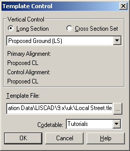
The template file being used is called "Local Street.tle" and the code table is should be set to "Local Street".
Attach Templates:
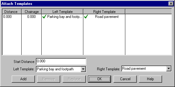
The templates "Parking bay and footpath" on the left and "Road pavement" on the right, have been attached from the start of the alignment.
Note that different templates can be applied to either side, and at any chainage or distance, in an implementation set.
Match Intersecting Surfaces:
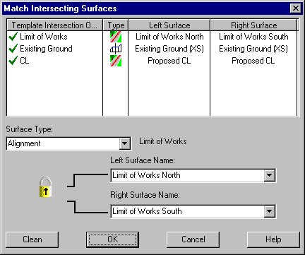
"Proposed CL" is the centre line primary alignment and is matched to the "CL" template intersection object.
The secondary alignments "Limit of Works North" and "Limit of Works South" are matched to the "Limit of Works" template intersection object.
The "Existing Ground (XS)" cross section set is matched to the "Existing Ground" template intersection object. Note that by using long sections along the "Limit of Works North" and "Limit of Works South" alignments, instead of the cross section set, problems with the need for clean intersections could be avoided.
Note the padlock icon, which can be "opened" or "closed" by clicking on the icon. If the padlock is closed, then when the left or right surface name is changed, the other surface name is automatically changed to match. If the padlock is open, as shown above, the left and right surface names can be changed independently.
Generally, when dealing with alignment or long section surfaces along secondary alignments, the left hand surface will be different to the right hand surface, and the padlock should be open. When dealing with cross section surfaces, primary alignments or long sections along primary alignment, the surface will be the same for both and therefore the padlock should be closed.
Modifications:
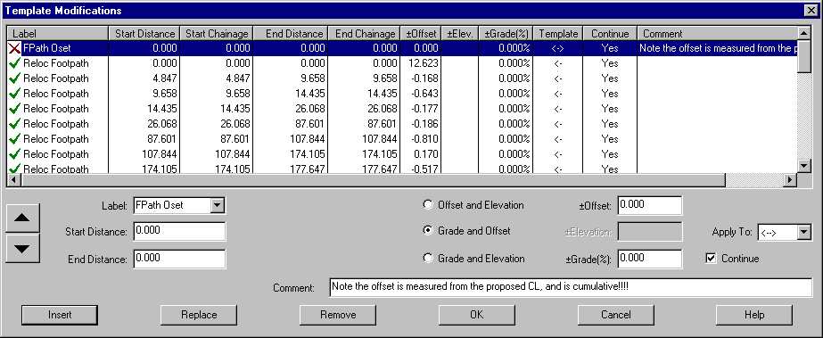
All modifications are to be applied to the left hand side template only.
The modifications have been arranged in four main groups. Each group is arranged by station (to assist with understanding and clarity of presentation). Each section has a heading that is a modification applied at a label not present in the template. These modifications are marked with a red cross, which helps to differentiate the groups.
The four main groups, from the start are:
- FPath Oset
Modifications are applied to the offset of the centreline of the footpath. The modification applies the change in offset from the design centreline to the centre of the footpath. In this case the changes are cumulative. The chainage and offset values were obtained from a Point from Alignment report.
- Pavement Width
These modifications control the pavement width, for the left hand side. The template has a kerb and channel at the narrowed width, so initially the pavement is extended to include the parking bay. Where the pavement is narrowed, the narrowing occurs over a chainage range (such as 116.779 to 125.267), whereas the widening are performed at a particular point (such as "between" 216.700 and 216.700).
- Alter K Profile
These modifications control the kerb profile or shape, changing from the barrier kerb to the semi-mountable kerb, and back again. They all occur at a single chainage and move the kerb face "out and down". Because the templates are incremental, the back of kerb is moved in, so that the total width of the kerb remains constant.
- FPath Exists?
The final set of modifications are used to control the test at row 13 of the template. These decide to either place or remove the footpath.
Output Parameters:
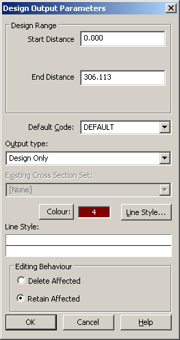
Select a suitable Colour and Line Style and check the output type is "Design Only".
In the main template implementation dialog:
Select to Open Cross Section in the currently open "Cross Section View".
Check the Cross Section Set name is "Proposed Ground (XS)".
Select Apply Template Implementation Set to create the "Proposed Ground (XS)" cross section set.
The descriptions for the "Existing Ground (XS)" cross section set have already been enabled. These show the location of the "proposed" alignments. In the Display Features dialog, for the "Proposed Ground (XS)" check on Template locations and the Section name line attribute.
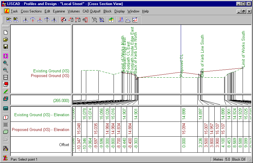
Step up and down the cross sections, and confirm that the footpath and kerbing have been created as required.
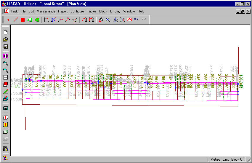
In the Display Features dialog, for the "Proposed Ground (XS)", check on Code point attributes. Note that the template could not process fully on the right hand side of the first section, and on the left hand side of the final section. ERR point codes were included in the template, to highlight these occurrences. These problems occurred because the design alignment is slightly skewed with respect to the original survey. The erroneous sections can be clearly seen in both the cross section view and the plan view.
In the cross section view, go to chainage 175.000, and zoom in on the footpath on the left hand side.
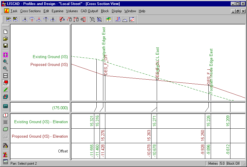
Note here that the edges of the footpath defined by the alignments are outside the points generated from the templates. This is because the width for the proposed footpath is measured perpendicular to the footpath centreline, whereas the width of the design footpath is measured along the section marker (i.e. perpendicular to the "Proposed CL" alignment).
Offsets in a template are always measured perpendicular to the primary alignment of the vertical control.
- FPath Oset
Conclusion
You have now completed this tutorial and have been exposed to the use of modifications to manipulate both vertical and horizontal designs.
You have also:
- Seen codes applied to points created by the template implementation set, to highlight where the template could not be correctly applied (i.e. "ERR" code);
- Learnt that the offsets in the template instructions are applied perpendicular to the control alignment;
- Seen that template tests, using modifications, can be used to vary a design with little relation to the cross section being processed;