To complete this tutorial you will require the Profiles
& Design module.
Note: This tutorial cannot be completed using LISCAD Lite.
The information in this tutorial builds upon the ideas and concepts presented in the tutorial "Using the Template Editor" and the tutorial "Template Implementation". Please ensure you are familiar with these before continuing.
Aim:
The aim of this tutorial is to demonstrate:
- The extension capability of the template instructions;
- The use of the default code in the template implementation set, and when transferring a cross section set to plan;
- Using different intersection surfaces for the left and right template;
The road pavement is to be widened. It is assumed that a survey has been taken of the crown and existing edges of the road pavement. The left hand side of the road pavement will be extended 3m, and the right hand side will be extended to a width, from the centre, of 10m. In both cases the existing crossfall of the road pavement will be maintained. This will be achieved using two separate templates.
Finally the design pavement's edges will be returned to plan.
Note that although in this example the edge of a road pavement is being described, the methodology applies equally to coordinating set out pegs beyond the edge of works.
Before You Begin:
Select this button to install the required data files.
- Review the Example Data Set
Select File/Open... and open the data file called "Pavement Rehabilitation.see".
Select Window/Section Manager... to view the alignments and sections currently in the data file.
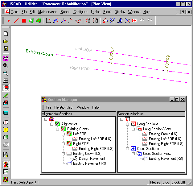
- The original survey consists of three lines that have been used to create alignments. The primary alignment along the road pavement centreline, called "Existing Crown", has two dependent secondary alignments, the left and right hand edge of pavement called "Left EOP" and "Right EOP" respectively.
- Long sections along each of these alignments have been created using key point objects. These long sections will be used to compute existing crossfalls, which will be used to obtain the elevations of the new road pavement edge.
- A 10m wide corridor of interest has been created for the primary alignment, "Existing Crown" (not displayed).
- Section markers have been created at 30m intervals. The section markers will be used for the generation of the edge points. By placing the section markers at a smaller interval, more detailed edge information will be created. Individual section markers can also be added to provide more detail where required.
- A cross section set called "Existing Pavement (XS)" has been created. It is not necessary to create the design, but will be used to check the result.
- An implementation set called "Design Pavement" has also been created.
In the Section Manager, click on the implementation set "Design Pavement" and then right click and select Edit Template Implementation Set from the pop-up menu.
It can be seen in the Control Parameters dialog of the implementation set "Design Pavement", that the template file "Pavement Rehabilitation.tle" is being used.
- Review the Cross Section Design Templates
Select Task/Utilities and then Tables/Template Editor... and open this file.
Note there are two tabs along the bottom of the Template Editor window, indicating that this file contains two different templates, called "Pavement Extension" and "Pavement Widening".
These templates use 2 codes:
- ERR - An error condition;
- DES_EDGE - The design edge of pavement.
We will start by examining the template "Pavement Extension".
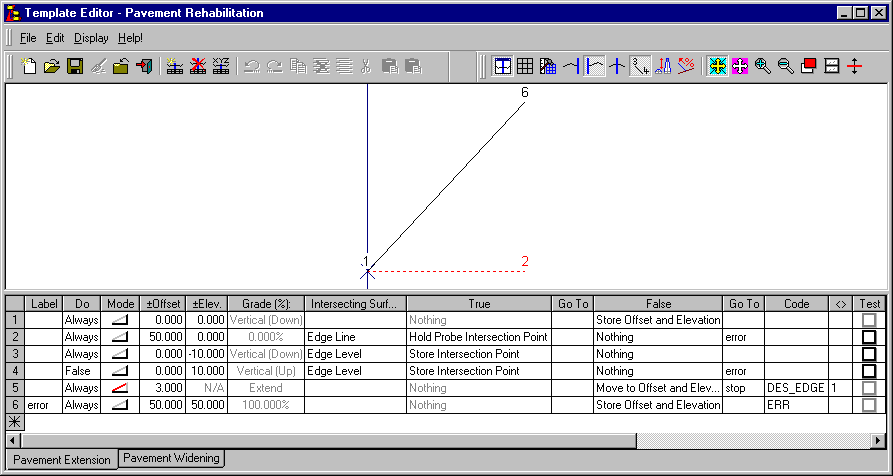
This template creates a point at the existing crown. Note that this point has NO code. This will be discussed later.
The "Edge Line" surface is the line of the surveyed edge of pavement, and is represented in the data file by the secondary alignments "Left EOP" and "Right EOP".
The "Edge Level" is the surveyed level of the edge of the road pavement. This is represented in the data file by the "Existing Left EOP (LS)" and "Existing Right EOP (LS)" long sections.
The first three rows in the template represent a straight line joining the "Existing Crown" to the road pavement edge.
The fifth row uses the 'extend' mode to continue the template on the previous crossfall, for a distance (offset) of 3m. A point with the DES_EDGE code is created at the existing edge and it moves the previous point to the new position. This will create the design point for widening of the left hand side of the road.
The final row creates an 'error' point. Please note that it does not indicate where in the template the error has occurred.
The other template in the file is called "Pavement Widening".
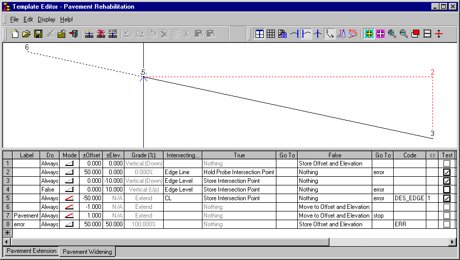
The first four rows of this template are similar to those of "Pavement Extension".
Row five uses the 'extend' mode to create a new point back on the centreline. This is the control point, from which the new pavement width will be measured. The previous rows having been used to determine the grade.
Note that a negative offset will move in the reverse direction to a positive offset. A template connected to the left of a long section can move to the right by using negative offsets.
Rows six and seven position the edge point. For the purposes of this exercise it has been decided that the pavement width will be controlled by a modification in the template implementation set, not by the template itself.
These rows move the design edge point a fixed distance beyond the centreline, and then the same fixed distance back. These rows appear to cancel each other out, but because the second row has a label, this allows the crossfall to be determined for the modification, therefore controlling the edge's final position.
- Apply the Templates to Create the Design Cross Sections
Select Task/Profiles & Design and then Profile/Template Implementation... to open and check the implementation set called "Design Pavement".
Control Parameters:
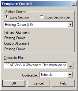
The template file is set to "Pavement Rehabilitation.tle" and the code table is set to "Tutorials".
Attach Templates:
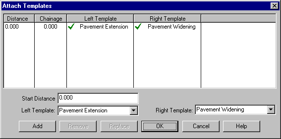
From the start of the alignment, the left template has been set to "Pavement Extension" and the right to "Pavement Widening".
Note that different templates can be applied to either side, and at any chainage, in an implementation set.
Match Intersecting Surfaces:
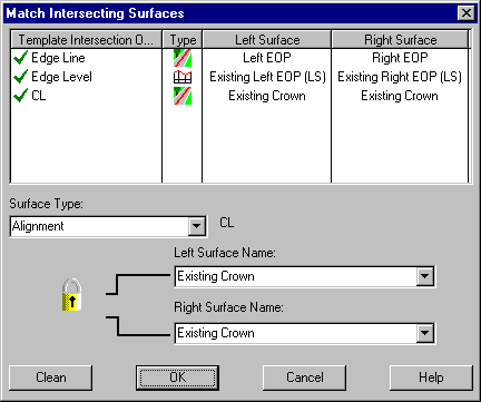
Match the template intersection object "Edge Line" to the "Left EOP" and "Right EOP" secondary alignments. "Edge Level" should be matched to the "Existing Left EOP (LS)" and "Existing Right EOP (LS)" long sections. Finally match "CL" to the "Existing Crown" primary alignment.
Note the padlock icon which can be 'opened' or 'closed' by clicking on the icon. If the padlock is closed, then when the left or right surface name is changed, the other surface name is automatically changed to match. If the padlock is open, as shown above, the left and right surface names can be changed independently.
Generally, when dealing with alignment or long section surfaces along secondary alignments, the left hand surface will be different to the right hand surface, and the padlock should be open. When dealing with cross section surfaces, primary alignments or long sections along primary alignment, the surface will be the same for both and therefore the padlock should be closed.
Modifications:
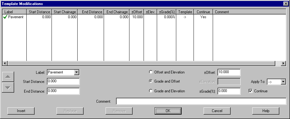
The modifications dialog is where the right hand pavement width is controlled. The grade is not changed, but the offset is the width for the specified side of the carriageway.
The offset can apply to the left, right or both sides of the carriageway. This is specified using the arrows in the Template column which is controlled by the Apply To field.
Output Parameters:
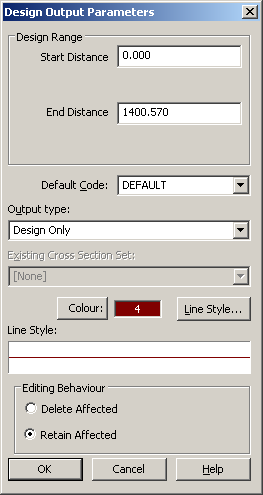
Select a suitable Colour and Line Style, check the output type is "Design Only" and that there is no default code set. By not selecting a default code any points without codes will be given the currently set point attributes.
In the main Template Implementation dialog check the Cross Section Set name is set to something appropriate like "Proposed Pavement (XS)".
Select the Apply Template Implementation Set button to create the "Proposed Pavement (XS)" cross section set.
- View the Design Cross Sections Created
To confirm the template has been applied correctly, open the newly created "Proposed Pavement (XS)" cross section in the same view as the "Existing Pavement" cross section set.
Right click and select Display Features from the pop-up menu, check on Template locations and Section name for the "Proposed Pavement (XS)" cross section set.
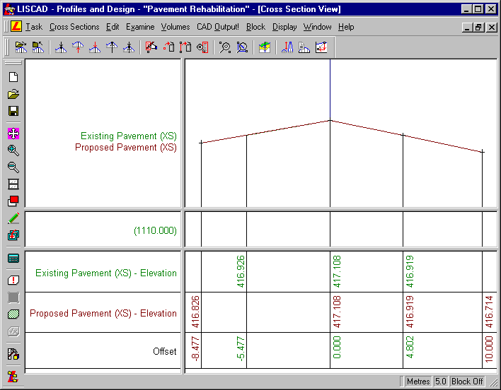
Examine the cross section, and note the offsets of the new edges, compared with the old, and that the sections lie on top of each other.
Select Display Features and turn on the Code point attributes for the "Proposed Pavement (XS)" cross section set.
Notice that the outermost points on each side have codes assigned to them. The 'Stringing ID' is displayed with the code (e.g. DES_EDGE/1). Stringing ID's create lines between points with the same code along the alignment when they are transferred to plan.
The points located on the "Existing Crown" and "Right EOP" alignments do not have codes. In the template and the implementation set, point code fields are left blank. Points in the cross section for which there is no code, will not be created in plan. These cross section points can be thought of as 'construction' points.
- Transfer the Design into Plan
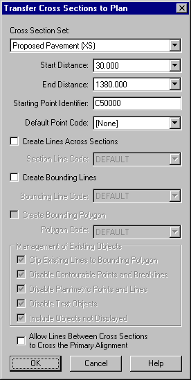
The last step is to select Cross Sections/Transfer Cross Sections to Plan... to transfer the "Proposed Pavement (XS)" points to plan. Set the Starting Point Identifier to 'C50000' so that it will not conflict with any existing point id's in the data file. Uncheck Create Lines Across Sections and Create Bounding Lines. The Default Point Code should be set to [None] so that the 'construction' points mentioned above are not transferred.
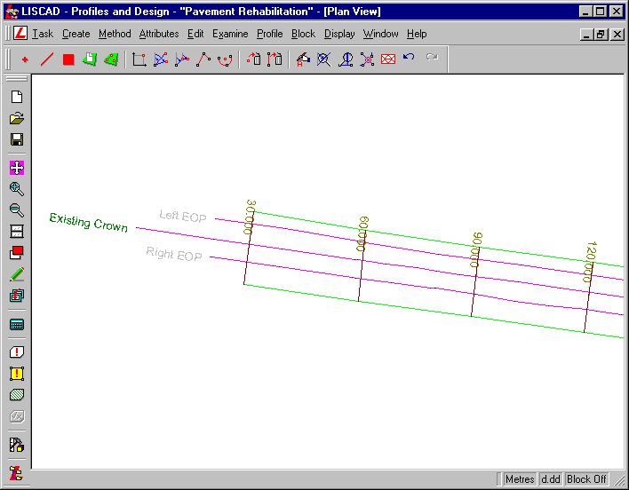
To confirm the points have been transferred correctly, open the plan view and examine the newly created points and lines.
Areas for Further Investigation:
In the Template Implementation dialog, open the Modifications and change the 10m offset. This will result in different pavement widths being created.
Conclusion:
You have now completed this tutorial and should have an understanding of the "extend" template instruction.
You have also:
- Used different templates on the left and right hand side of a control line;
- Learnt about the effects of using blank codes;
- Seen that a design can, and should, be checked in the system;
- Observed that the Profiles and Design functions provide versatile methods to create points and lines for a variety of purposes, not necessarily for traditional design purposes.