In this tutorial you will create a terrain model using survey data, that you will use to create contours for a plan.
You will learn how to:
- Configure a layer for terrain model data
- Set objects to be used in a terrain model
- Set objects as breaklines
- Create a boundary that will define the extents of your terrain model
- Create holes in your model using boundaries
- Create a terrain model
- Segment breaklines
- Display contour lines
- Create contour lines
- Create contour text
45 minutes
Terrain module
Open a Project
- Click
 to access the File menu, then click Open.
 - In the Open dialog, navigate to \Documents\Tutorial Data\, then select Terrain Model.neo and click Open.
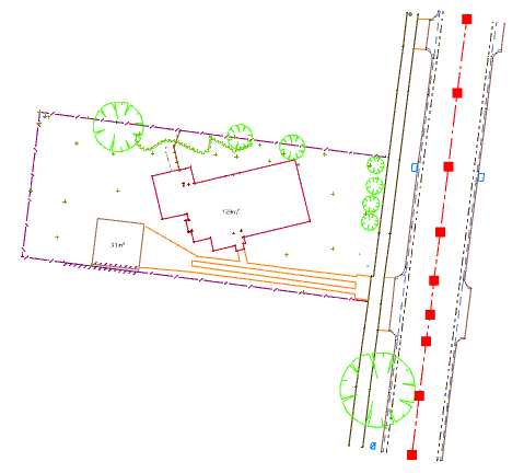
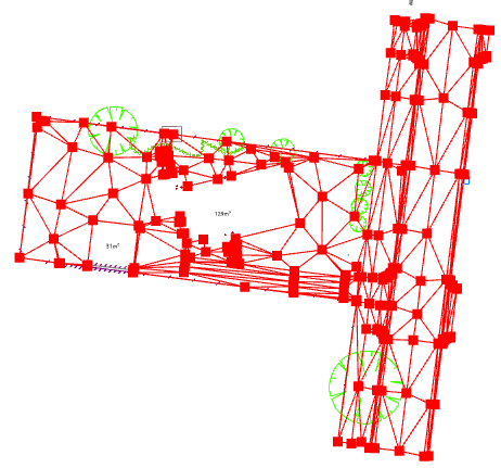
The data from a feature survey of a lot and the abutting road is displayed. Before you create a terrain model, you need to classify objects depending on if they are suitable to be used in the terrain model . In addition, you need to determine the location of breaklines and boundaries to be used in the formation of the model.
Set Data to be used in a Terrain Model
The layer the data was imported to determines its default terrain model settings.
- On the ribbon Home tab, in the Tools group, select the Attributes checkbox to display the Attributes tool window.
-
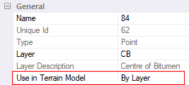
In the Model view, click the line (Unique Id:5) representing the centre of the road.
In the Attributes tool window, in the General category, note that the lines Use in Terrain Model property is set to By Layer.
Not all data is suitable to be used in the terrain model. For example, measurements to objects above or below the ground surface should not be used to generate a terrain model of a natural surface. You can automatically set if objects are to be used in the terrain model, using the layer definition.
- On the ribbon, in the Layer group, click
 Adopt, to make the selected line’s layer the active layer.
 -
On the ribbon, in the Layer group, click
 Edit to view the Layer dialog. On the General tab, note that the Use in Terrain Model checkbox is selected.
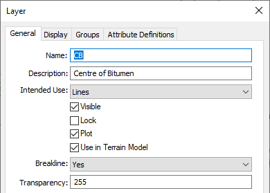
-
Click Cancel.
Any objects stored on this layer, with the property ‘Use in Terrain Model’ set to ‘By Layer’ will be considered for use in the terrain model.
- On the ribbon, in the Tools group, select the Layers checkbox to display the Layers tool window.
- In the
 column, double click the FL (Floor Level) layer to display the Layer dialog.
 -
To exclude the floor levels from the terrain model, clear the Use in Terrain Model checkbox, then click OK.
Any objects stored on this layer, with the property ‘Use in Terrain model’ set to ‘By Layer’ will not be used in the terrain model. You can override the layer setting by setting the ‘Use in Terrain Model’ property on the object to ‘Yes’ or ‘No’ rather than ‘By Layer’.
- On the ribbon in the Select group, click
 beside
  All, then select Texts.
 -
In the Attributes tool window, in the General category, click Use in Terrain Model, then click
 and select No.
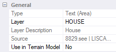
Define Breaklines
A line object can be set to be a breakline. Setting a line to be a breakline will cause the model to form triangle edges along the line, preserving the lines grade.
| Lines will only be used as breaklines if all vertices in the line have a defined height (i.e. not a default height). |
- In the Layers tool window, in the column, double click the CB (Centre of Bitumen) layer to open the Layer dialog.
In the General tab, the Breakline property is set to Yes. Any lines imported to, or created on this layer will have the 'Breakline' property automatically set to 'Yes'. Click Cancel.
This setting only applies to an object when it is imported or created. If you change the setting in the layer definition it will not update the objects that are already on the layer. -
On the ribbon in the Tools group, click the Query checkbox to open the Query tool.
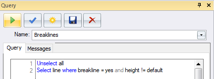
The Breaklines query that was previously created in the project, selects all lines where their Breakline property is set to Yes and does not have any vertices with a default height. These are the breaklines that will be used when the terrain model is generated, providing they do not cross other breaklines or boundaries.
-
Click
 to run the query.
The breaklines are highlighted in red.
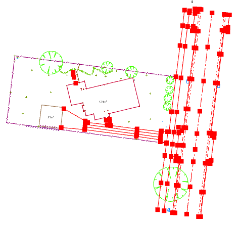
Grades of lines defining the road features, paths, toe of the embankment and the driveway will be preserved and used to form triangle edges when the terrain model is formed. Defining breaklines results in your formed surface being a more accurate depiction of the surveyed surface. The top of the embankment should also be a breakline.
- In the Layers tool window, in the column, click the TOB layer.
In the toolbar, click
, then select Lines to select the line representing the top of the embankment (Unique id 1). 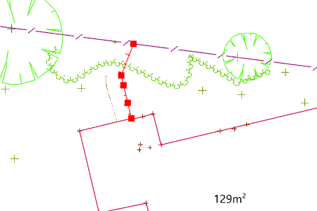
In the Attributes tool window, in the General category, click the Breakline property, then click
and select Yes.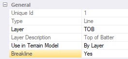
Create a Boundary
Boundaries are used to define the extents of the model or create areas not to be modelled. In this tutorial, you will create a model with two holes where the shed and the house are located. To do this you need polygons defining the edge of the buildings that have their ‘Breakline’ property set to ‘Boundary’.
- On the ribbon Home tab, in the Select group, click the beside then select Polygons.
-
In the Attributes tool window, in the General category, click the Breakline property, then click
and select Boundary.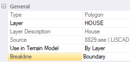
Boundaries are only used in the terrain model computations when each vertex in the polygon has a defined height (i.e. no default height). The building polygons are not sufficient to create the desired model. If you were to create a model at this stage, with the two boundaries selected, only the boundaries and objects inside the boundaries would be considered in the terrain model formation. You will add an additional boundary around the extents of the data. The effect of this is that all data within the external boundary but not within the internal boundaries will be used to generate the terrain model.
Rather than creating a polygon manually by selecting each vertex at the extents of the data, you will create the polygon that approximates the extents of the data automatically. You will then modify the polygon, so it is suitable to use as a boundary for your data.
- On the ribbon, in the Layer group, click the Active Layer box, then select MBDY (Terrain Model Boundary).
- On the ribbon, in the Tools group, select the Create checkbox to display the Create tool window.
- Select
 Polygon from the objects menu.
 - Select
 Straight from the segments menu.
 - Select the
 Boundary method.
 -
Type External Boundary in the Name box.
To form an accurate model, the boundary must only contain vertices that will be used in the terrain model formation.
- Select the Exclude objects with ‘Use in Terrain Model’ off checkbox.
- Select the Exclude vertices with default height checkbox.
On the ribbon, in the Select group, select
All.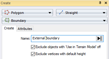
-
In the Create tool window, click OK.
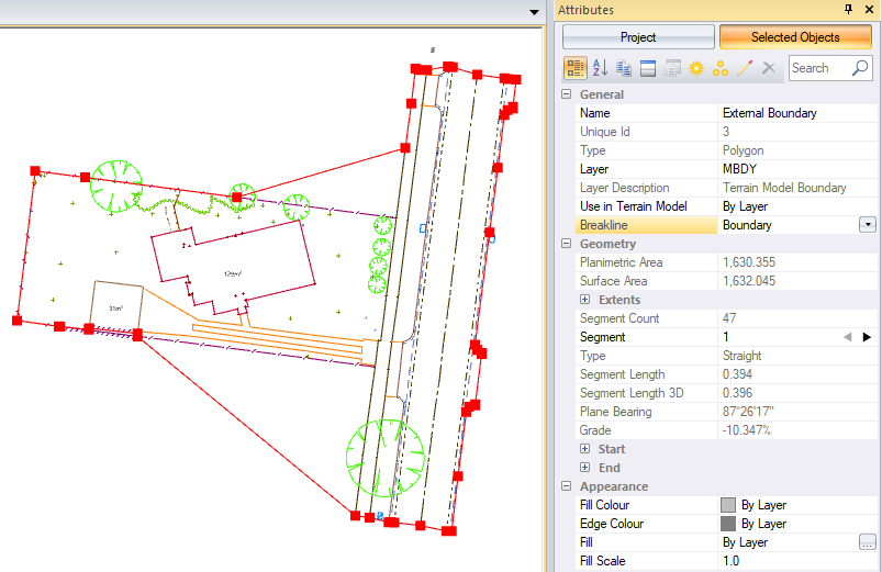
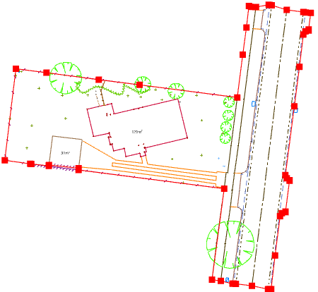
A polygon is created that surrounds the selected data. The polygon created is automatically set to be a boundary as the MBDY layer definition has the ‘Breakline’ property set to ‘Boundary’.
You will now edit the boundary where the lot abuts the road to avoid unnecessary triangles being formed.
- On the ribbon in the Tools group, click the Modify checkbox to display the Modify tool window.
- Select the
 Insert Vertex method.
 -
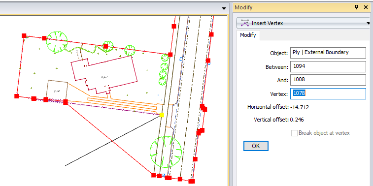
Click the Object box then in the model, click the boundary polygon where it cuts the corner at the north lot boundary then tentatively select the vertex shown in the diagram below to fill the Vertex box.
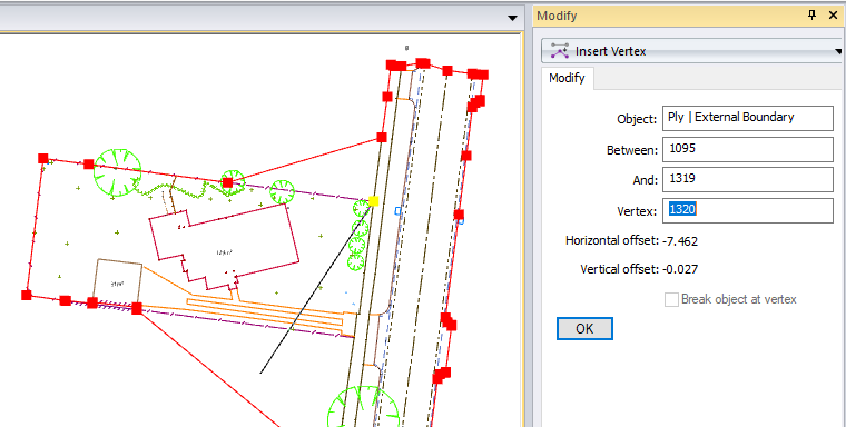
- Ensure the values match the diagram above, then click to accept the tentative selection and insert the vertex. (If these values do not display, continue to tentative select until the correct vertex display or type the values in to the controls.)
-
Click the polygon where it cuts the corner on the south lot boundary then tentative select the vertex shown in the diagram below to fill the Vertex box.
-
Ensure the values match the diagram above, then click to accept the tentative selection and insert the vertex.
You should also insert points that are on or near the boundary into the boundary. You will do this for one of the points on the north boundary.
- In the Layers tool window, click the column for the MBDY row, then press Ctrl and click the NS row.
Click
, then select All.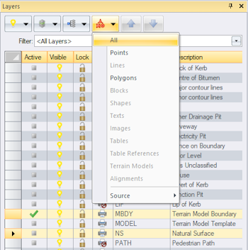
- On the ribbon, in the Layer group, click
 Isolate to only display selected items in the model view.
 - Press Esc to deselect the objects.
- On the ribbon, in the Tools group, click the Options checkbox to display the Options tool window.
- In the Labels category, select the Point Names checkbox.
- In the Modify tool window, remain in the Insert Vertex pane and click the Object box then click the polygon in between point 1335 and 1318 on the north boundary. Ensure the Object box displays Ply | External Boundary, the Between box displays 1319 and the And box displays 1317, then pick the point 1318 to insert the points vertex into the boundary.
- In the Layers tool window, on the toolbar, click
 then select All On.
 In the Options tool window, in the Labels category, clear the Point Names checkbox.
You now have the required boundaries to create a terrain model with holes where the buildings are.
If you were to create another polygon inside the house polygon and set it as a boundary then objects inside the smaller internal polygon would be triangulated creating an island.
Create a Terrain Model
You will create a terrain model on a new layer.
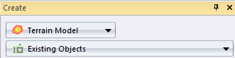
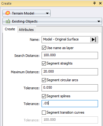
- Click the Create tool window, then select Terrain Model from the object menu.
Select the Existing Objects method.
- Type Model – Original Surface in the Name box.
- Select the Use name as layer checkbox to automatically create a layer using the terrain model name and the layer template defined for the project.
-
Type 100 in the Search Distance box.
The search distance gives you control over how triangles are formed over areas where data is sparse. If a vertex is not found within 100 meters of another triangle vertex, a triangle edge will not be formed between the two vertices.
If your data covers a large area and your surface points are spaced further away, then you should increase the search distance. -
Select the Segment straights checkbox. Type 20 in the Maximum Distance box.
This setting will force the edge of the triangle formed along the boundary (and any other line used to create the terrain model) to be no longer than 20 metres.This will prevent long skinny triangles being created on longer straight sections. The vertices created will preserve the grade of the line but will only be connected to the terrain model. (The created vertices will not be inserted into the line.)
Curved lines are approximated when the terrain model is formed. If the curved lines are not segmented only the start and end point (and midpoint if it exists), are used to generate the model. You will segment the circular arcs and splines to better approximate the curved lines representing the road’s kerb.
- Select the Segment circular arcs checkbox.
- Type .05 in the Tolerance box for the circular arcs.
- Select the Segment splines checkbox.
- Type .05 in the Tolerance box for splines.
-
Clear the Segment transition curves checkbox, since there are not any transition curves in the project.
-
On the ribbon, in the Select group, click
All.While this selects data that you may not want in the terrain model, the 'Use in Terrain Model' setting will determine if the object is used in the terrain model formation.
Prior to generating the terrain model, you should validate to check for crossing breaklines, vertices with default heights or coincident vertices caused by multiple objects in the same location but with different heights.
Click Validate.
A Create Terrain Model Report view tab displays in the work area.

The report indicates that breaklines cross, and the line’s vertex ids are reported.
If you continue to compute the terrain model without resolving the warnings, a terrain model will be created but the issues will be resolved automatically and some of your data may be ignored. In this case, one of the breaklines will be discarded. Lets investigate the cause of the warning.
- On the ribbon, in the Tools group, select the Find checkbox to display the Find tool window.
- Click the object menu, then select
 Vertex.
 - Type 2 in the Id box, then click Find.
- Click the Model view tab to view the selected object.
On the ribbon in the View group, click
beside  Fit, then select Selected to zoom into the selected objects.
The vertex belongs to a line representing a change in grade at the top of an embankment.
In the Find tool window, type 19 in the Id box then click Find.
In the Find tool window, type 40 in the Id box then click Find.
The vertices belong to the external boundary. The warning is indicating that top of the embankment crosses the boundary.
-
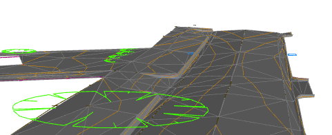
Using the mouse zoom into the crossing breaklines.
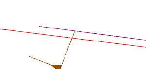
Inserting a vertex into the boundary has caused the breakline representing the top of the embankment to cross the boundary. A boundary also acts as a breakline, and two conflicting heights are computed at the location where the lines cross. You will resolve this issue by inserting vertex 2 into the boundary.
If it is not valid to resolve a crossing breakline warning by inserting a vertex from one line into another or clipping or moving a line, you should decide which line you want to be a breakline. - In the Modify tool window, remain in the Insert Vertex pane, and click the Object box, then in the Model view click the selected boundary near the top of embankment line.
-
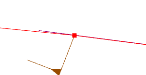
In the Model view, right click the vertex at the end of the line representing the top of the embankment until 1105 displays in the Vertex box and the breakline is tentatively selected.
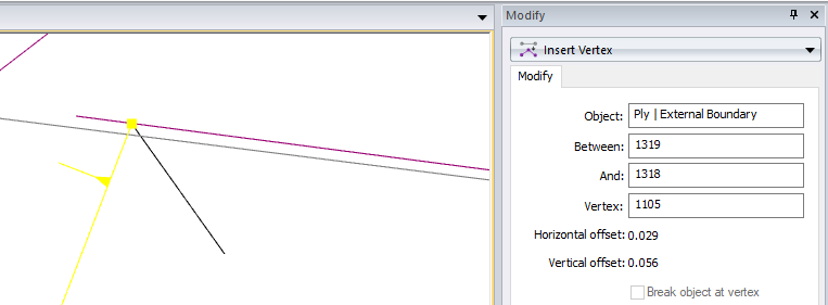
Ensure your values match the diagram above, then click in the Model view to accept the selection and insert the vertex into the boundary.
The breakline and boundary now share the same vertex so there will not be any conflicting heights at this location.
- On the ribbon in the View group, click Fit, then click the Model view tab and press Ctrl A to select all the displayed data in the Model view.
-
In the Create tool window, on the Terrain Model pane, click Validate.
A message displays indicating the terrain model has been validated successfully.
Click OK in the message box.
Now that you have validated your data you will create the terrain model.
In the Create tool window, click OK to form the terrain model.
- On the ribbon, in the Select group, click
 None.
None.
Review the Terrain Model
You will examine the model, display the contours and view the model in 3D view looking for any unexpected spikes.
- In the Layers tool window, click the column for the MBDY row, then press Ctrl and click the BCK, INVand the HOUSE row.
In the toolbar, click
, then select All.
Note the following: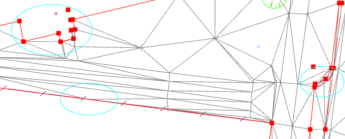
- Triangles have not be formed inside the internal boundaries.
- Triangles have not be formed outside the external boundaries.
- A vertex has been inserted into the terrain model to form triangles with shorter edges along the longer straight section of the southern lot boundary. This is because you selected to segment straights when you created the terrain model. The vertex has not been inserted into polygon.
- Vertices have been inserted into the terrain model to approximate the curves representing the back of kerb and the invert of the curve. This is because you selected to segment circular curves and splines when you created the terrain model. The vertices have not been inserted into the lines.
- On the ribbon, in the Select group, click None then in the View group, click .
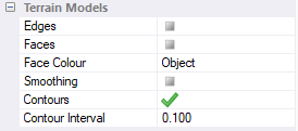
- In the Options tool window, select the Contours checkbox from the Terrain Models category.
- Type 0.1 in the Contours Interval property.
Clear the Faces and Edges checkboxes.
View the contours in the Model view. This is where you would check that they are a good representation of the surveyed property.
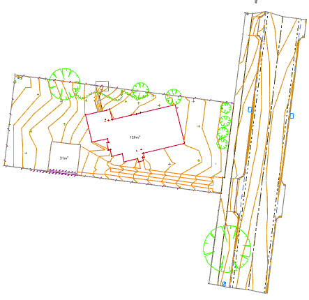
These contours are for display purposes only. If you want to print or export contours, you need to create line objects.
You can select the Contour Heights checkbox in the Labels category to display the contour heights.- In the Options tool, in the Terrain Models category, select the Edges and Faces checkboxes.
- In the Scaling category, click the Vertical Exaggeration setting and type 2 so you can easily see the change in grade when you view the model in 3D.
- On the ribbon, in the View group, click beside
 3D, then select Perspective if the option is available. (If the option is unavailable, 3D view is already displaying a perspective view. Click 3D.
 - On the ribbon, in the View group, click
 Rotate.
 Click and hold the left mouse button, then move the mouse to rotate the data so that you can see the triangles formed on the road, kerb and near the embankment breakline that you edited. Use the mouse scroll button, to zoom and pan.
Viewing in 3D view may highlight points, or vertices in breaklines or boundaries, that have height errors or should not have been used in the terrain model. You should resolve any errors or consider removing the object from the terrain model formation. If you make any changes to the data’s geometry, 'Use in Terrain Model', or 'Breakline' properties, you should form a new terrain model.
On the ribbon, in the View group, click
 Plan then click to fit the data in the view window.
To delete an unwanted terrain model, on the ribbon, in the Select group, click
beside . then click Terrain Models and select the name of the terrain model. In the Edit group, click  .
.
Create and Annotate Contours
Now create line objects to represent the contours and then use these lines to create contour text.
- In the Options tool, in the Terrain Models category, clear the Contours, Edges and Faces checkboxes,
- In the Create tool window, select Line from the object menu.
- Select Straight from the segment type menu.
- Select the Contours by Existing Terrain Model method.
- Click
 in the Terrain Model box, then select Model - Original Surface.
 - Type .5 in the Major Interval box.
-
Type .1 in the Minor Interval box.
So that contour lines can be displayed in different colours and with different line thicknesses, you will place the major and minor contour lines on separate layers.
- Select the Create contours on separate layer checkbox.
- Click in the Major Layer box, then select CONTOUR - Major.
- Click in the Minor Layer box, then select CONTOUR - Minor.
Select the Smooth the contours checkbox.
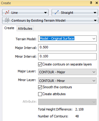
Click OK.
The contour lines display in the Model view.
If you were to export your projects data, these contour lines would be exported as line objects. On the ribbon, in the Select group, click
None.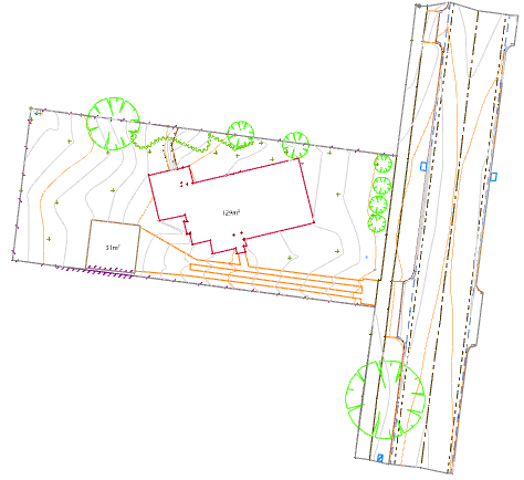
- To annotate the contours, click the Create tool window, then select
 Text objects.
 - Select the
 Contour text type.
 - Select the
 Segment Distance method.
 - Ensure Contour displays in the Style list.
- Type 30 in the Distance box.
- On the ribbon, in the Layer group, click the Active Layer list and select CONTOUR - Text
- On the ribbon, in the Select group, click beside All, then select Major Contour Lines
Click OK to create text for the major contour lines.
The 'Contour' text style in the project specifies that text for contours is created in the uphill direction so some of the contour text display upside down.
The CONTOUR - Text layer is drawn after the CONTOUR - Major layer so that the background for the text overlays the contour lines and provides a buffer around the text.
On the ribbon, in the Select group, click
None.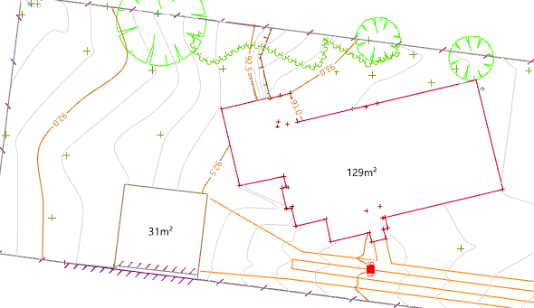
Sometimes it is necessary to move the contour text.
- Right click to tentatively select the text selected in the diagram above (Unique id:12).
- On the ribbon, in the Edit group, click
 Move Object(s).
 Click and drag the text to the straight section of the contour, then click
 to rotate the text so that it is parallel to the line. Click to accept the rotation.
Your data is now ready to create a topographic plan with contours.
You have learnt how to set data to be used in the creation of a terrain model and how to create a terrain model with a hole using boundaries. You should now understand the difference between created contours and displayed contours and how to annotate created contours.
If you have any questions please contact: support@listech.com.
