You can use control codes to perform powerful operations that create linework and symbols for a feature survey. While it is possible to create most linework on-board Leica Captivate, or by using other line creation techniques, control codes extend the linework creation capabilities of the field controller, performing more complex tasks not possible by other methods. In this tutorial you will learn how to use control codes to:
- Create linework with tangential circular arcs and three-point circular arcs
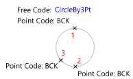
- Create a circle representing a round-about
- Size and orientate a rectangle using attributes
- Size and orientate a symbol using attributes
- Create an underground pipe from surface points and attributes
- Create linework representing stairs
- Create a line at an offset from another line
45 minutes
Xchange Leica Survey Module
Open the Project
- Click
 to access the File menu.
 - Click Open, then navigate to Documents\Tutorial Data and open the project Coding Control.neo.
- On the ribbon Home tab, in the Tools group, select the Layers checkbox. A list of layers in the project is displayed in the Layers tool.
Edit the Layers
You will edit the WBEL (Water – Underground) layer to include an attribute that can be used in conjunction with the control code action that creates subsurface pipes.
- In the Layers tool, in the
 column, double-click the row containing the WBEL layer to display the Layer dialog.
 - Click the Attribute Definitions tab.
- Click
, then click Real8.
- Type Depth in the Name box, then click OK.
- Click OK, to accept the changes.
Define Control Codes
You will define control codes to create circular arcs, rectangles, circles, steps, subsurface pipes, symbols, and offset a line.
- On the ribbon Manage tab, in the Configuration group, click
Control Codes.
- In the
 column, double click the row containing the Leica DBX Control Codes.
A list of previously entered control code actions and their definitions are displayed. Depending on the control code action, you can define:
- The name of the control code.
- A description for the control code that will display in Leica Captivate.
- Whether the control code is passed to Leica Captivate as a free code.
- The name of attributes to be used as input parameters for the control code action.
You can find a description of each control code action, the syntax and the parameters required in the online help
. For Leica Captivate, control codes are recorded as free codes and most parameters as attributes of the free code.
Before creating a codelist that includes these free codes, you will add and edit some definitions.
- Click
to add a new control code action.
-
Click in the new row in the Action column and select Arc Start (Tangential), then click
to automatically insert [{0=ArcTanStart} Description=Start tangential arc] in the Value column.
In the above definition:
- The square brackets indicate that the control code and the description will be exported to Leica Captivate.
- ArcTanStart is the name of the control code. This will be the name of the free code that you will see in Leica Captivate.
- The control code name is included in {}.
- ‘0=’ indicates the control code name will follow. This is primarily used when the control code parameters precede the control code in the definition. In the case above, {ArcTanStart} would be sufficient.
You can define whatever name you like for the control code. -
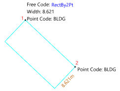
Notice that there are two definitions for the Rectangle by Edge action since a rectangle can be created using two different methods. In this tutorial you will use the rectangle by 2 points and a width method which is the first definition in the list. This method requires a parameter {1} which defines the width of the rectangle.
In the definition [{0=RectBy2Pt} {1:Width} Description=Rectangle by 2 pts & width]:
- {1: Width} indicates the width parameter, {1}, will be input using an attribute named Width.
- {1: Width} is enclosed in the square brackets so Width will be exported to the Leica Captivate codelist as an attribute of the free code RectBy2Pt.
- Click in the Value column in the row with the second definition for the Rectangle by Edge action. Remove the [] from the definition because in this tutorial you will not use the control code RectBy3Pt and do not want to output the control code to the Leica Captivate codelist.
-
View the Value for the Symbol Add action.
This action sizes the point symbol and creates an additional point with a different symbol and symbol dimensions. It is designed to have the control code name with the same name as an existing layer.
A point code recorded in a Leica Captivate data file can execute a control code action in the same way a free code can. A layer TREE exists with the attributes Spread and Trunk.
You will edit the attribute name for the second parameter in the definition so the Trunk attribute will be used for the size of the symbol for the additional point.
-
Click in the Value box for the Symbol Add action and edit the definition to {0=Tree} {1:Spread} {2:Trunk}.
You have the option of specifying an additional layer with this definition which is used to determine the symbol and layer for the additional point. The definition {0=Tree} {1:Spread} {2:Trunk} is not enclosed in square brackets because the control code Tree does not need to be exported as a free code to the Leica Captivate codelist. The TREE layer and the associated attribute definitions will be exported as a point code to the codelist.
-
Click
, then click in the new row in the Action column and select Subsurface Diameter.
The Subsurface Diameter topic, in the help, outlines the parameters that you are required to input:
- The depth of the pipe at each of the surface points.
- The pipes diameter(s).
- Where the depth measurement to the pipe is taken to.
-
Click in the new row in the Value column, then type [{0=SubSurfDiam}] Depth [{2:Diameters} {3:Depth Location (Inv=I,Obv=O,CL=M)} Description=Subsurface Feature with Diameter.
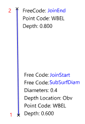
You defined the Depth attribute on the layer WBEL earlier. This attribute will contain the pipe depth below the surface point. The Diameters and Depth Location attributes will be exported to the Leica Captivate codelist as attributes of the SubSurfDiam free code. The Depth Location attribute will contain a pick list of 3 options (Inv, Obv, and CL) that will also be exported to the codelist. When the control codes are processed these values will be translated to the required I, O, and M values respectively.
-
Click OK.
You will notice the Value entry is highlighted in red. This is because an error in the definition has been detected.
-
Hover the mouse pointer over the Value and view the message that displays beneath the cursor.
All open brackets need a corresponding closed bracket. The Brackets do not Close message indicates this requirement has not been met. In this case there is not a closing square bracket at the end of the definition. You will not be able to accept your changes until the definition validates.
- Type ] at the end of the definition, then click OK to accept your changes.
-
Click Close.
The LISTECH - Alpha template includes a list of fully defined control codes.
Export a Code List
Control codes can be exported when you create a codelist.
-
On the ribbon Home tab, in the Data group, click
 below
below Export, then click Leica DBX Codelist.
If Leica DBX Codelist is not listed in the menu, click Add/Remove to add it. - In the Save As dialog, click Options.
- Click in the Control Codes box, then click
 and select Leica DBX Control Codes.
 - Click OK.
- Navigate to the Code folder in the data storage device that you will plug in to the Leica Captivate controller.
- In the File name box, type Codes and Free Codes.
Click Save, then load these files onto your Leica Captivate controller.
Control codes within the square brackets will be exported as free codes. The attributes, within square brackets, defined for these control codes, will be exported as attributes of the free code. Layers will be exported as point codes and layer attributes as attributes of the point codes.
When a new job is created in Leica Captivate, you can select this codelist from the list of available codelists.
Collect Data in the Field
Using the codelist you just created, field data was collected with Leica Captivate:
- Free codes were accessed via the F7 hotkey.
- Attribute values were input for the free codes.
- Free codes were recorded.
- Points were measured and assigned point codes.
- Attribute values were input for the point codes.
The following explains how features were recorded using Leica Captivate with the codes and attributes assigned.
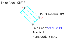
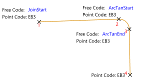
In the diagrams:
- A cross represents the measurement location.
- Red numbers indicate the order the measurements have been recorded.
- Manually measured dimensions used for attributes required by the control code action are displayed in brown.
- The code that will action the control code action is displayed in Blue.
| Freecodes and their attributes must be recorded before the measurement. |
| Feature | Assigned Codes and Attributes. |
|---|---|
| Tree |  |
| Building |
 |
| Side Entry Pit |
 |
| Steps |
 |
| Edge of Bitumen |
 |
| Round-about |
 |
| Underground water pipe |
 |
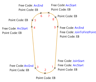
| Traffic Island |
 |
Data for all other features is collected using the Leica Captivate on-board coding functionality.
Use control code actions to create linework when:
|
| An Arc Start (Tangential) control code action must be paired with an Arc End (Tangential) action, and an Arc Start (Non-tangential) action must be paired with an Arc End (Non-tangential) action. |
Import Measurements
You will now import the data that was collected in the field. If measured points do not have a code they will be placed on the active layer. For this tutorial, the STN layer will be set as the active layer.
- On the ribbon Home tab, in the Layer group, click in the Active Layer box, then select STN.
-
On the ribbon Home tab, in the Data group, click
 below
below Import, then click Leica DBX.
If Import, is disabled, click the model view to make it the active view.
If Leica DBX is not listed in the menu, click Add/Remove to add it. - Click Options, then in the Coding category, select the Process Codes checkbox.
- Click the Control Codes box, then click
 and select Leica DBX Control Codes.
 - Ensure the String Number Attribute box and the Join Consecutive Points checkbox are cleared because points will be joined using control codes and the Leica Captivate on-board coding functionality.
Click OK.

- In the Open dialog, navigate to Documents\Tutorial Data\Coding Control_0001_0921_161444 then select Control Codes_0001_0921_161444.XCF.
Click Open to import the file.
The imported data displays in the model view.
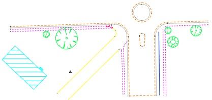
Points and lines are imported to the layer matching the code. Codes that match control code names execute control code actions, creating lines, polygons, shapes, and sizing point symbols. Some points to note when control code actions are executed are:
- Measurements and attributes are used to size and orientate point symbols, rectangles, and circles.
- Where control code actions require more than one measurement, the next measurements with the same code as the first measurement are used.
- When a closed figure is formed, the intended use of the layer determines if a line or polygon is created.
- Lines are ended when either a JoinEnd code or another JoinStart code is encountered for a measured point with the same code.
- When tangential arcs are created, the previous and next points in the line are used to define the tangent.
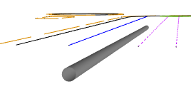
A pipe is created below the surface using the SubSurfDiam control code and the line created on the WBEL layer.
-
Linework representing the stairs in 3 dimensions is created using the StepsBy3Pt control code.

- Free codes and their attributes are added to the measurement’s code in the Measurements view, so they are available should you want to reprocess the measurements
- The control code value defined for the control code action determines the format of the free code and their attributes in the measurement code. For example the Steps by Edge control code action has a value [{0=StepsBy3Pt} {1:Treads} Description=Steps by 3 pts] and the Treads attribute value is 3, so StepsBy3Pt 3 is added to the code in that order.
While most symbols and linework looks correct there are two issues that you will need to resolve.
Edit and Reprocess Codes
Linework and symbols are created on import, however, it may be necessary to edit the codes and reprocess if control codes or attributes were entered incorrectly.
First you will turn off layers that do not require editing, and display point names.
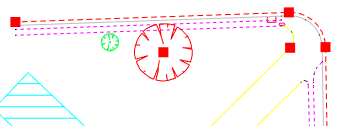
In the model view, select a tree, and a line representing the edge of bitumen, as shown in the diagram.
- On the ribbon Home tab, in the Layer group, click
Isolate to turn off all layers not represented in the current selection.
- On the ribbon Home tab, in the Tools group, select the Options checkbox to display the Options tool. Click the drop-down menu, then click Display.
- In the Features category, select the Vertices checkbox and in the Labels category, select the Point Names checkbox.
On the ribbon Home tab, in the Tools group, select the Attributes checkbox to display the Attributes tool.
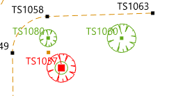
The Trunk attribute for one of the trees was mistakenly entered as 2.2 in the field.
-
In the model view, select the tree with the name TS1057.
-
In the Attributes tool, scroll down to the Attributes category and click in the Trunk box. Edit the value to 1.2 and then press Enter.
When codes are reprocessed the trunk symbol will be redrawn with the new diameter.
Point TS1017 should be the end of a line representing the edge of the bitumen, however, a control code action to start a new line at point TS1044, was inadvertently forgotten. This has caused the continuation of the first line and the creation of an undesired line segment between points TS1017 and TS1044.
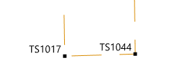
You could delete the line segment, but instead you will change the code to include a new control code and reprocess the measurements. To begin a new line at point TS1044 you will need to either enter a JoinEnd control code for point TS1017 or a JoinStart control code for point TS1044.
- On the ribbon Measurements tab, in the View group, click
New Measurements View. A new Measurements view is displayed.
In the tree control, click At: STN1 (Known Back Sight) beneath the Measurements node and the Total Station Setups node.
The measurements are displayed in the table, on the right-hand side of the Measurements view.
You can right-click the table column heading, then click Columns to display a menu that enables columns to be toggled on and off. Look at the code for the measurement to point TS1044.
The code is EB. Since the line sequence beginning at point TS1000 with the JoinStart control code and the EB point code, has not been ended until point TS1063, point TS1044 is part of this line sequence. This point, however, should be the start of a new line sequence that represents the edge of bitumen on the opposite side of the road. You will edit the code to include the Join Start control code which will end the previous line and start a new line.
In the Code column, click the box for the measurement to point TS1044 and replace the value with EB JoinStart, then press Enter.
The point created from the measurement, will be the start of a new line sequence of points with the EB code.
- On the ribbon Measurements tab, in the Process group, click
Options to display the Edit Measurement Processing Options dialog.
- In the Coding category, select the Process Codes checkbox. Click in the Control Codes box, then select Leica DBX Control Codes and click OK.
In the tree control, beneath the Total Station Setups node, click At: STN1 (Known Back Sight) to select the station setup to process.
All data beneath the selected node in the tree control is processed. - On the ribbon Measurements tab, in the Process group, click
Process to reprocess the selected station setup.
- Click the Model tab. The undesired line segment between points TS1017 and TS1044 is gone. Also, the point symbol for the trunk is now sized with the new Trunk attribute value.
Data Editing
Using control codes will ease the amount of data editing required in the office. There is one issue to fix where a spline recorded in the field was given the PATH code, however a small portion of the spline is part of the driveway. You will break the spline and assign the smallest portion to a different layer.
In the Layers tool, in the Visible column, click
for the DWAY and PATH layers, then click
for the EB layer.
The PATH and DWAY layers will now be visible.
Zoom in on point TS1023.
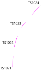
The spline segment between points T1023 and T1024 is the edge of the driveway, however, it is currently displayed as the path.
- On the ribbon Home tab, in the Tools group, select the Modify checkbox to display the Modify tool.
Select Break from the method drop-down list then click point TS1023 and click OK.
The line is broken at the selected vertex. You will now change the layer of the line segment.
- Click
Select to return to sselect mode, then select the line segment between points TS1023 and TS1024.
- Click the Attributes tool, then in the General category, click in the Layer box and select DWAY.
- On the ribbon Home tab, in the Select group, click
None to deselect the line segment. The line segment’s appearance is now determined from the DWAY layer.
- In the Layers tool, click
then click On to turn on all layers.
- In the Options tool, on the Display page, clear the Vertices and Point Names checkboxes.
Zoom out to view your finished feature survey.
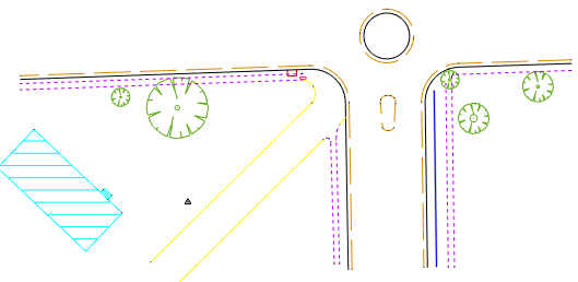
Applying Control Codes in the Office (Advanced)
As you saw earlier, control codes can be applied after the field data is imported by adding a control code and its parameters to the measurement code. It was noted in the field that the kerb for the traffic island was offset from the edge of the bitumen by 0.3 metres horizontally and 0.05 metres vertically.
You will use the line offset control code action with the definition [{0=LineOffset} {1:Feature Code} {2:Horizontal Offset} {3:Vertical Offset}] to create the line representing the back of kerb.
- Click the Measurements view tab.
-
For the measurement to point TS1070 click the Code box, then on the ribbon Measurements tab, in the Edit group, click
Edit. Add LineOffset BCK 0.3 0.05 to the end of the code, then click OK.

- In the tree control, beneath the Total Station Setups node, click At: STN1 (Known Back Sight) to select the station setup to process.
-
On the ribbon Measurements tab, in the Process group, click
Process.
Click the Model tab.
In addition to creating a line representing the edge of bitumen for the traffic island, a second line offset 0.3 metres to the right and 0.05 metres higher is created on the Back of Kerb layer.

You could enter this control code in the field when the edge of bitumen for the traffic island is recorded.
You have completed the tutorial and learnt how to use control codes on-board a Leica Captivate controller to increase productivity in the field or the office.
If you have any questions please contact: support@listech.com.
- This method can be used in conjunction with other coding methods.
