You can use numerous methods to code measured points for the purpose of creating linework including:
- Joining consecutive points with the same code
- Using codes and string numbers
- Using codes and control codes that define how to construct objects when the codes are processed
- Using onboard functionality supported by your field controller
This tutorial shows how you can use feature codes to apply plan symbols, line styles, and use consecutively measured points with the same code to form straight lines or polygons. You will export a code list to and import measurement data from the Leica FlexLine instrument, however, the concept is the same for all field controllers.
You will learn how to:- Create layers that use specific line styles, plan symbols and attributes
- Set the intended use of a layer to define the way linework is formed
- Create lookup tables to map layer names and attribute names
- Export a code list
- Automatically create linework by joining consecutive points with the same code
- Import objects to layers using codes
- Size plan symbols using attributes
- Edit codes and reprocess
- Edit linework and symbols that were created using coding
35 minutes
Leica Survey Module
Set System Settings
- Click
 to access the File menu.
 - Click Options, then click Model View Context Menu.
- Click the Choose commands from: list, then click Display Options.
- Select Display Point Names, then click Add >>.
- Click OK.
Open the Project
- Click
 to access the File menu.
 - Click Open, then navigate to Documents\Tutorial Data and open the project Coding Consecutive.neo.
-
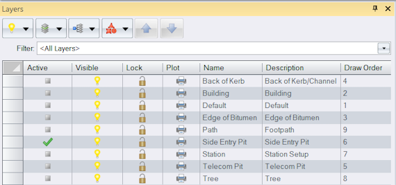
On the ribbon Home tab, in the Tools group, select the Layers checkbox. A list of the layers in the project are displayed in the Layers tool.
Edit the Layers
You will edit the Side Entry Pit layer so that attributes collected in the field are used to determine the dimensions of the associated plan symbol. First you will define attributes for the layer.
- In the Layers tool, in the
 column, double-click the row containing the Side Entry Pit layer.
 - In the Layer dialog, click the Attribute Definitions tab.
- Click
, then click Real8.
- Type Width in the Name box, then click OK.
- Click
, then click Real8.
-
Type Length in the Name box, then click OK.

- Click the Display tab.
Click the Type list, then select Point.
Any point placed on the Side Entry Pit layer will be represented by the box symbol (S002) and drawn in grey (808080). The value in the Width box is the distance in the x-direction and the value in the Length box is the distance in the y-direction when no rotation is applied to the symbol. You can edit the layer so that attributes collected in the field are used to determine the dimensions of the symbol in preference to predefined dimensions.
- In the Dimension Attribute category click in the Width Attribute box.
Click
 to view a list of attributes defined for the layer, then select Width.
- Click the Length Attribute box, then click
 and select Length.
 -
Click OK.
Similarly, the layer TREE uses the Spread attribute to define the dimensions of the tree symbol.
-
In the Layers tool, in the
 column, double-click the row containing the Building layer to display the Layer dialog.
The Intended Use for this layer is currently set to Lines. This means when measured points are assigned the building code, and codes are processed, they could be joined with lines. However, the linework will not close back to the first point in the line sequence. You can choose to do this using the Create tool, however, in this tutorial you will change the intended use of the Building layer to polygons so that a closed figure is formed automatically.
-
Click in the Intended Use box, then select Polygons from the list.
Any points measured in the field or lines created from coding that are placed on a layer will use the layer settings. You can edit a layer to set the point symbols, line styles, attributes, colours etc. for that layer. Blue has already been selected as the colour for points and lines on this layer. You will now edit the appearance for polygons.
- Click the Display tab.
- Click the Type list then select Polygon.
- In the Appearance category, click in the Fill Colour box. Click
 then select Blue (0000FF) from the colour palette.
 - Click the right side of the Edge Colour box to automatically display the colour palette, then select Blue (0000FF).
-
Click in the Fill box, then click
 and select the last fill in the list (H026). Click OK.
- Click OK to accept the changes to the Building layer.
Edit Lookup Tables
As the FlexLine software limits code and attribute names to 8 characters, you will edit a lookup table to abbreviate some names.
- On the ribbon Manage tab, in the Configuration group, click
.
- In the Manage Lookup Tables dialog, click in the Type box then select Layer.
-
In the
 column, click the row containing the FlexLine Layer lookup table, then click
 .
Most of the existing layer names have already been mapped in the Foreign column.
- Click
, then in the new row, click in the Local column. Click
 then select Building from the list of existing layers.
 -
In the same row, click in the Foreign column then type BLDG. Click OK.
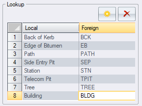
When this lookup table is selected during export of a code list, the layer with the name Building will be exported as a code named BLDG.
- Click in the Type box, then select Attribute Definition.
-
In the
 column, double-click the row containing the FlexLine Attributes lookup table.
Most of the attributes names you will use are 8 characters or less and do not need to be abbreviated.
- Select Description in the Foreign column, then edit the name to ‘Desc’ and click OK.
- Click Close.
Export a Code List
Layers have been created for all codes required in the field. You can now export a code list that contains layer names as code names and layer attributes as code attributes.
-
On the ribbon Home tab, in the Data group, click
 below
below Export, then click Leica FlexLine Codelist.
If Leica FlexLine Codelist is not listed in the menu, click Add/Remove to add it.
- Click Options.
- Clear the String Number Attribute box, as you will not use string numbers in this tutorial.
- In the Lookup Tables category, click in the Layer box, then click
 and select FlexLine Layer.
 -
Click in the Attribute Definition box, then click
 and select FlexLine Attributes.
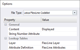
Each layer will be mapped to the abbreviated value as specified in the lookup table and exported as a code.
You can also use a lookup table to map a layer or attribute name to a blank name, which means the name will not be exported to the code list. - Click OK.
-
Type the name Code list in the File name box, then click Save.
You can now upload the code list to the Leica FlexLine Instrument and select it as the code list for the job.
You can export code lists to numerous instrument manufacturer's field controllers.
If additional codes are required that were not included in the code list, you can add them in the field.
Any unrecognised codes assigned to measured points in the field will be used to automatically create layers on import.
Collect Data in the Field
Using the code list you just created points were measured in the field.
- Points that were assigned a code SEP had a value entered for the Length and Width attribute.
- Points that were assigned the code TREE had a value entered for the Spread attribute.
- Points that were part of an open line were assigned a line code.
- Points that were part of a closed line were assigned a polygon code.
- Points that were part of a line have been measured in sequence without interruption.
Import Measurements
You will now import the data that was collected in the field. If measured points do not have a code, they will be placed on the active layer. For this tutorial the Station layer will be set as the active layer.
- On the ribbon Home tab, in the Layer group, click in the Active Layer box, then select Station.
-
On the ribbon Home tab, in the Data group, click
 below
below , then click Leica FlexLine.
If Leica FlexLine is not listed in the menu, click Add/Remove to add it.
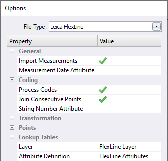
- Click Options, then in the Coding category, select the Process Codes checkbox and the Join Consecutive Points checkbox.
- Clear the String Number Attribute checkbox.
- In the Lookup Tables category, click in the Layer box, then click
 and select FlexLine Layer.
 -
Click in the Attribute Definition box, then click
 and select FlexLine Attributes.
- Click OK.
-
In the Open dialog, navigate to Documents\Tutorial Data then select Coding Consecutive.xml. Click Open to import the file.
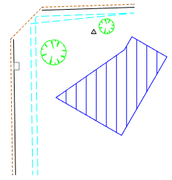
When the data is imported the following occurs:
- Codes assigned to points are mapped to a layer using the selected lookup table and the points are placed on that layer.
- Points that do not have codes are placed on the active Station layer.
- The point plan symbol for the layer, is assigned to the point. If dimension attributes were defined for the layer the point’s attributes are used to size the symbol.
- Attributes collected in the field are stored with the point.
- Since Join Consecutive Points was selected in the import options, for points that are placed on a layer with the Intended Use set to Lines or Polygons, consecutive points with the same code are joined in the order they were collected and a line or polygon object is created.
Consecutive points are only joined if the points do not already belong to a join sequence using an alternate join method.
If a lookup table maps a layer name to a blank value then points without codes are mapped to that layer.
If a code cannot be matched to a layer name, or an attribute cannot be matched to a attribute definition, a new layer or attribute definition is created.While most symbols and linework looks correct there are several issues that you will need to resolve.
Edit and Reprocess Codes
Linework and symbols are created on import, however, it may be necessary to edit the codes and reprocess if codes were entered incorrectly.
First you will turn off layers that do not require editing, and display point names.
- In the Layers tool, press and hold the Ctrl key then in the
 column, click the Edge of Bitumen and Telecom Pit rows. Release the Ctrl key.
 - At the top of the Layers tool, click
and then click Off.
- On the ribbon Home tab, in the Tools group, click the Options checkbox to display the Options tool window. Click the page menu, then click Display.
In the Labels category, click the Point Names checkbox.
You set the intended use of the Building layer to Polygon, so a polygon has been formed on the Building layer using all consecutive points with the BLDG code (points 2015 - 2019).
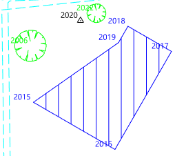
Point 2020 was placed on the Station layer because it was inadvertently not assigned a code in the field. The point represents the corner of the building and it was intended that the point would be assigned a code BLDG and be included in the BLDG sequence.
- On the ribbon Home tab, in the Tools group, click the Attributes checkbox to display the Attributes tool.
- In the model view click point 2020, then in the Attributes tool, in the General category, click the Layer box. Click
 , then select Building from the list of existing layers.
 -
On the ribbon Home tab, in the Select group, click
None to deselect the point.
While changing the layer has changed the appearance of the point it is still not part of the building polygon. You could insert the vertex into the polygon, but instead you will change the coding and reprocess the measurements.
- On the ribbon Measurements tab, click
New Measurements View.
-
In the tree control, click At: 2 (Known Back Sight) beneath the Measurements node and the Total Station Setups node.
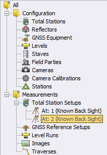
The measurements are displayed on the right-hand side of the Measurements view.

Since a lookup table was used you will enter the field code not the layer name.Right-click anywhere in the table, then click Columns to show or hide columns. -
In the Code column, click the Code box for the measurement to point 2020, then type BLDG.

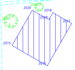
The point created from the measurement to point 2020, will be placed on the Building layer and be joined to other points in the BLDG sequence.
- On the ribbon Measurements tab, in the Process group, click
Options to display the Edit Measurement Processing Options dialog.
-
In the Coding category, click in the Layer Lookup box, then click
 and select FlexLine Layer.
This will map the field codes to the appropriate layers when the codes are reprocessed.
-
Select the Process Codes checkbox and the Join Consecutive Points checkbox, then click OK.
The building points were collected from two stations, so to preserve the complete BLDG sequence you will process all the setups together.
-
In the tree control, select the Total Station Setups node to select all of the station setups to process.
All data beneath the selected node in the tree control is processed. - On the ribbon Measurements tab, in the Process group, click
Process.
-
Click the Model tab. Point 2020 is now included in the building polygon.
Data Editing
- In the Layers tool, in the
 column, click the row containing the Side Entry Pit layer. Click
 , then click Points to select the side entry pit in the model view.
-
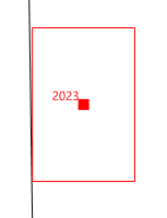
Using the mouse scroll wheel, zoom in on the selected side entry pit (point 2023).
-
View the side entry pit in the Attributes tool.
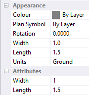
The colour and plan symbol has been determined from the Side Entry Pit layer. The width and length of the plan symbol have been determined from the Width and Length attributes values entered in the field and displayed in the Attributes category, however, the side entry pit needs to be slightly rotated to make it parallel to the back of the kerb.
- On the ribbon Home tab, in the Tools group, click the Modify checkbox to display the Modify tool window.
- Click the method drop-down menu, then click Rotation.
- In the model view, pick the line from point 2007 to 2008 representing the back of kerb.
- Select Parallel in the Mode control, then click OK to rotate the side entry pit to be parallel to the back of kerb.
-
On the ribbon Home tab, in the View group, click
to zoom to the extents of the project.
When you imported the file you may have noticed some issues with the linework representing the back of kerb and the path.
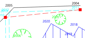
You can see the lines representing the back of kerb are not connected between points 2005 and 2007, even though all points were given the code BCK. To understand the reason for this, look at the order that the points were collected. The BCK sequence started at point 2004 and continued with point 2005. Point 2006 was assigned a TREE code and the BCK sequence was broken. A new BCK sequence was then started at point 2007.
If points are measured in the incorrect order in the field, you cannot resolve the issue by reprocessing the codes. You will use the Modify and Create tools to resolve the issue.
- On the ribbon Home tab, in the Layer group, click in the Active Layer box, then select Back of Kerb.
- On the ribbon Home tab, in the Tools group, select the Create checkbox to display the Create tool.
- Click the object drop down menu, then click Line.
- Click the segment type drop-down menu, then click Straight.
-
Click the method drop-down menu, then click Existing Vertex.

- In the Model view, right-click point 2005 to tentatively pick the point. When you are confident you have correctly picked point 2005, click in the model view to accept the points vertex as the first in the line.
- In the Model view, pick point 2007, then in the Create tool, click End.
- In the Modify tool, click the method drop-down menu, then click Join.
- Pick the line between points 2004 and 2005, then the line between points 2005 and 2007. Click OK to join the line.
-
Pick the line between points 2007 and 2008, then click OK so that all three line segments are joined as one line.
The edge of the path between points 2009 and 2010, should be represented by a separate line. The join between points 2010 and 2011, was unintended. The points 2009 to 2014, were collected consecutively and were all assigned the PATH code. There was not a break in the path sequence to establish the end of the first line and the start of the next line. The point 2022 representing the tree could have been measured in-between point 2010 and 2011 to break the line, however, it may not always be possible, in the field, to break the line with a different code. In this case, you should edit the line after importing or use an alternative coding method for creating linework.
- In the Modify tool, click the method drop-down menu, then click Delete Segment.
- In the Model view, pick the line between points 2010 and 2011 to delete the unwanted segment.
- In the Options tool, clear the Point Names checkbox.
-
In the Layers tool, click
and then click On.
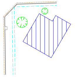
You have completed the tutorial and learnt how to use field codes in conjunction with the join consecutive points coding method to create linework. It is a simple method but the order that the points are required to be collected is important.
If you have any questions please contact: support@listech.com.
- This method can be used in conjunction with other coding methods.
