Import a feature survey to become familiar with layers.
You will learn how to:- Create and edit a layer
- Place layers in layer groups
- Edit a lookup table
- Place imported objects on layers
- Make a layer active
- Use a layer to control the appearance of objects
- Use attributes to control symbol sizes
- Filter layers
- Control the visibility of layers
- Lock a Layer
30 minutes
Leica Survey Module
Open the Project
- Click
 to access the File menu.
 - Click Open, then navigate to Documents\Tutorial Data and open the project Layers.neo.
-
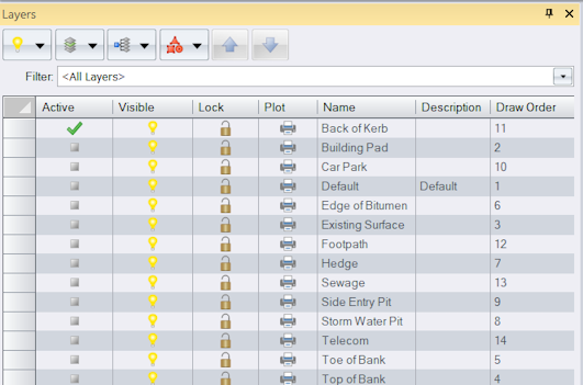
On the ribbon Home tab, in the Tools group, select the Layers checkbox. The Layers tool window displays and a list of the layers in the project are shown.
Create a New Layer
You will create a layer for trees and define their appearance in the model view.
- On the ribbon Home tab, in the Layer group, click
New to display the Layer dialog.
-
In the Name box, type Tree.
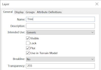
- In the Intended Use list, select Points, because trees are primarily point objects.
- Click the Display tab and in the Type list, select Point.
-
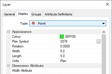
In the Appearance category:
- Click in the Colour box, then click
 to display the colour picker. Select the colour Lime (00FF00), fourth colour on the top row.
 - In the Plan Symbol box, click
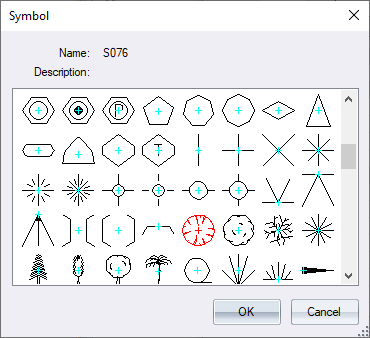
 to display the Symbol dialog. Scroll down and select the tree symbol (S076) shown in the dialog below.
- Click in the Colour box, then click
-
Click OK to close the Symbol dialog.
-
In the Appearance category, click the Units box, then click
 and select Ground, to use ground measurements to define the symbols size.
You will now define two attributes that can be added to points placed on this layer.
-
Click the Attribute Definitions tab.
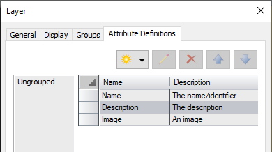
- Click
, then select Integer.
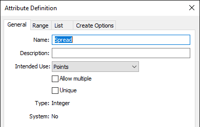
- In the Name box, type Spread.
-
In the Intended Use list, select Points, because the attribute will be valid for points only, then click OK.
- Click
, then select Text.
- In the Name box, type Species.
-
In the Intended Use list, select Points then click OK.
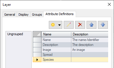
- Click OK to accept the layer definition.
Create a Layer Group
Layer groups are used to group similar layers. You will now create a layer group and add the Tree layer to it.
- In the Layers tool window, click
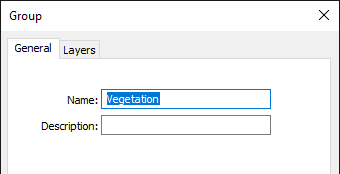
, then select New to display the Group dialog.
-
In the Name box, type Vegetation.
-
Click the Layers tab and in the Included column, select the checkbox for Hedge and Tree to add these layers to the group.
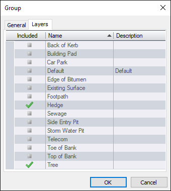
A layer can belong to multiple groups. - Click OK.
Edit a Layer Lookup Table
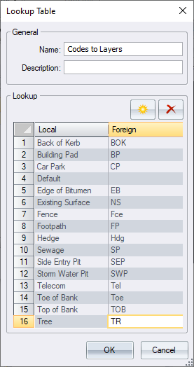
You will edit a layer lookup table to map imported objects assigned the code TR to the Tree layer you created earlier.
-
On the ribbon Manage tab, in the Configuration group, click
Lookup Tables.
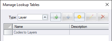
- Ensure Layer is selected in the Type list. Select Codes to Layers from the list, and click
.
-
Click
to add a new row to the list. In the Local column, click in the new row, then click
 and select Tree from the list. In the Foreign column type TR.
-
Click OK, then click Close in the Manage Lookup Tables dialog.
When this lookup table is selected during import, all objects with the code TR will be mapped to the Tree layer.
Import Data to Layers
You will now import feature survey data. The codes assigned to objects will be used to determine which layers they are placed on.
- On the ribbon Home tab, in the Data group, click
 below
below then click HeXML.
- In the Open dialog, click Options.
-
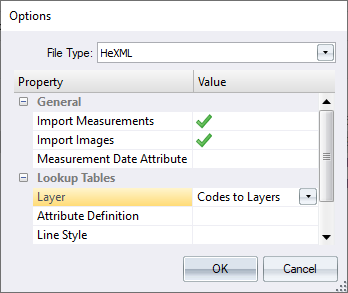
In the Lookup Tables category, click in the Layer box, then click
 and select Codes to Layers from the list.
- Click OK.
- In the Open dialog, navigate to Documents\Tutorial Data, select the file LayerData.xml, then click Open.
- The field data should be imported successfully, and the lookup table has been used to map the objects to the desired layer. Close the import report if it displays.
Clean up Data
If an object does not have a code it will be placed on the active layer unless a lookup table maps the blank code to a layer. The lookup used on import, maps objects with blank codes to the Default layer. You will select all objects on the Default layer and change the layer they are placed on.
- On the ribbon Home tab, in the Tools group, select the Attributes checkbox. Dock the Attributes tool window next to the Layers tool window.
-
In the Layers tool window, select the Default layer by clicking the Default row in the
 column.
Many of the commands in the Layers tool window apply to selected layers. - In the Layers tool window, click
then click All. You have selected all objects on the selected layer.
-
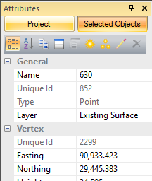
The point selected was not given a code in the field. The Attributes tool window is displaying the selected point. To change the layer of the point, in the General category, click the Layer box and select Existing Surface from the list.
-
To confirm the Default layer is now empty, in the Layers tool window, click in the Filter box and select <Unused Layers>. The Default layer is listed so you can safely delete the layer. Select the Default layer, click
, then click Delete.

When you delete a layer all objects on the layer are deleted. The layer Fence has been created automatically because the code FCE was found in the imported data and mapped to the layer Fence using the lookup table. Layers created on import are based on the default settings when a template layer is not defined.
You can set a template layer in the Manage Layer menu in the Layers tool.
You will now edit the line style for the Fence layer. To easily view the line style change in the model view, you will turn off all other layers.
- In the Layers tool window, click in the Filter box and select <All Layers>.
-
Select the Fence layer, then click
and click Lines.
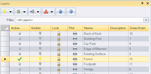
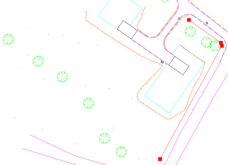
The line on layer Fence has been selected in the model view.
- On the ribbon Home tab, in the Layer group, click
Isolate to isolate the selected Fence layer. This has turned off all layers other than those whose objects are selected in the model view.
- In the Layers tool window, select the Fence layer.
- Click
and click Edit.
- In the Layer dialog, click the Display tab then select Line from the Type list.
-
Click in the Line Style box, then click
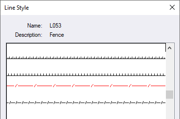
 . In the Line Style dialog, select the Fence line style (L053), then click OK.
-
Click OK to accept the changes. As the lines line style is configured to 'By Layer', you will see the line style updated in the model view.
When there are a large number of layers you can filter by layer groups to help you easily find a layer. Filtering can also alter the visibility of layers in the model view.
- Click
, and select Auto Isolate.
-
In the Layers tool window, click the Filter box and select the layer group Vegetation from the list.
Only layers in the selected layer group are displayed in the list of layers. Auto Isolate has altered the visibility of the layers. You can see that objects on the Tree and Hedge layer are displayed in the model view and the Fence layer object is not displayed.
You can clear the Auto Isolate option if you do not want filtering to alter the visibility settings for the layers. - In the Layers tool window, in the Visible column, click
for the Hedge layer to hide the hedge objects.
-
Select any tree from the model view.

In the Attributes tool window you can view the symbols current width and length in the Appearance category.
When the data was imported the tree symbol width and length were set based on those specified in the Tree layer. You can view the tree's actual spread in the Attributes category. This value was entered in the field. Now you will edit the layer definition to use the Spread attribute value to size the tree symbol.
- On the ribbon Home tab, in the Layer group, click
Adopt to adopt the selected layer as the active layer, then click
Edit.
- In the Layer dialog, click the Display tab. Select Point from the Type list.
-
In the Dimension Attribute category, click in the Width Attribute box, then click
 and select the attribute Spread from the list.
-
Click in the Length Attribute box, then click
 and select the attribute Spread from the list. Click OK.
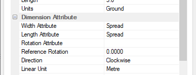
The trees in the model view are now drawn using their attribute value. You would normally set this up prior to import so that the tree symbols are sized on import.

Add an Attribute
You can add other attributes for the tree object but only if the attribute is defined in the layer attribute definition. Earlier we created the attribute Species in the Tree layer. You will now add this attribute to the selected tree.
- In the Attributes tool window, click
.
- In the Create Attribute dialog, select Species (Text) from the Attribute list.
-
In the Value box, type Gum, then click OK.
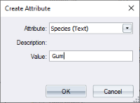
The attribute is added to the selected tree and can be viewed in the Attributes tool window.
Work with Multiple Layers
Some actions can be performed on multiple layers.
-
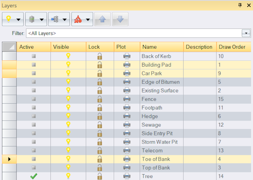
In the Layers tool window, click in the Filter box and select <All Layers> to display all of the layers in the project.
You will now select multiple layers using the Ctrl and Shift keys to add or remove a layer from the selection.
- In the Layer tool window, select the Back of Kerb layer. Press and hold the Shift key and select the Car Park layer, then release the Shift key. All layers between the first and last selection are selected.
- Press and hold the Ctrl key and in the in the
 column, click the Footpath, Toe of Bank and Top of Bank layers, then release the Ctrl key.
 -
The Ctrl key toggles the selection of the layer. Press and hold the Ctrl key and click the Footpath and Back of Kerb layers. Release the Ctrl key. The two layers were removed from the selection since they were already selected.
-
In the Visible column, click
for the Building Pad layer. You can see all selected layers have been turned off.
Only objects on visible layers can be selected in the model view.
Annotate Polygons
When objects are created they are placed on the active layer. You will create text on the Building Pad layer to annotate the building pads with their area.
- To set the active layer, in the Layers tool window, in the Active column, select the checkbox for the Building Pad layer. The layers visibility is automatically turned on.
-
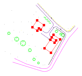
On the ribbon Home tab, in the Select group, click
 alongside
 All. Click Polygons.
- On the ribbon Home tab, in the Tools group, select the Create checkbox.
- Dock the Create tool window with the Layers tool window.
- In the Create tool window, select Text from the list of objects.
-
Select Area from the list of text types.
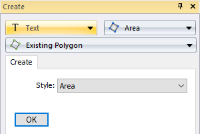
- Click OK to create linked text objects that display the area of the selected building pads.
-
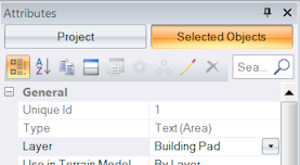
Select one of the text objects and view the properties in the Attributes tool window. You can see that the text has been placed on the Building Pad layer which is the active layer.
Lock a Layer
When a layer is locked you can select objects on the layer and create new objects on the layer but you cannot edit any objects on the layer.
-
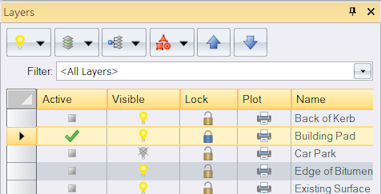
In the Layers tool window, in the Lock column, click
for the Building Pad layer.
- On the ribbon Home tab, in the Edit group, you will notice
is disabled preventing you from deleting the selected text object.
Exclude a Layer from a Plot
There may be a layer you do not want to include in your plot.
-
In the Layers tool window, in the Plot column, click
for the Existing Surface layer.
Display All Layers
-
In the Layers tool window, click
, then select All On to display all layers in the model view.
You have completed the tutorial and learnt how to create and manage layers, use a lookup table to map data to specific layers, and use layers to control how objects appear in the model view.
If you have any questions please contact: support@listech.com.
