Compute the offset from objects, reference lines and reference planes, to a vertex.
Home / Tools / Examine / Offset
| Control | Description |
|---|---|
| Mode |
Existing Object - Input the object. Reference Line - Input the reference line. Reference Plane - Input the reference plane. |
| Convention |
Select one of the following:
|
| Object | Input the line or alignment to compute the offset from. |
| Reference Line | Input the reference line to compute the offset from. |
| Reference Plane | Input the reference plane to compute the offset from. |
| Vertex | Input the vertex to compute the offset to. |
| Project start/end segments |
Do one of the following:
|
| Project at external deviation |
Do one of the following:
|
| Horizontal Offset | The offset on the horizontal plane, perpendicular to the Object. |
| Vertical Offset | The vertical offset from the horizontal plane. |
| Distance | The reduced distance from the start of the line to the location on the line determined from the Horizontal Offset. |
| Chainage | The chainage along the alignment to where the offset is computed from. |
| Grade (%) | The grade from the location on the line determined by the Horizontal Offset, to the Vertex. |
| Grade (Ratio) | The grade between the two vertices as a ratio. |
| Grade (Angle) | The vertical angle between the two vertices. |
| 3D Offset | The offset from the line, computed in 3 dimensions. |
| 3D Distance | The slope distance from the start of the line to the location on the line or projected line where the 3D offset is computed from. |
- Options available depend on the Mode selected.
- Configure the Distance Type in Units Options.
- Where multiple offsets can be computed, the smallest offset is reported.
- An asterisks indicates the offset is to a projected line segment .
- A reference line is considered to be of infinite length when computing offsets.
- If the Convention is Above / Below and the reference plane is vertical, an offset will not be displayed.
- If a user coordinate system is selected the difference in Z is displayed.
- Where two offsets are reported the offset order reflects the direction of the line or alignment. The first offset is for the segment that is first.
- Intercardinal displays the prefix N, NE, E, SE, S, SW, W or NW to indicate the approximate direction of the vertex from the line.
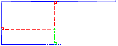
| Project start/end segments | ||
|---|---|---|
 |
 |
Line Projected Line Projected Offset Offset Vertex |
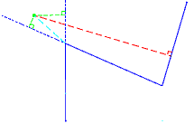
| Project at external deviation | ||
 |
 |
Line Projected Line Projected Offset Radial Distance Offset Vertex |
