To complete this tutorial you will require the Profiles & Design module.
Note: This tutorial cannot be completed using LISCAD Lite.
The information in this tutorial builds upon the ideas and concepts presented in the tutorial "Using the Template Editor" and the tutorial "Template Implementation". Please ensure you are familiar with these before continuing.
Aim
The aim of this tutorial is to explain the instructions in a template and create a Template Implementation Set which will create a road, in cut, with benching.
Two different cases of benching will be considered:
- The elevation of the benching is controlled by the design of the road, minimising earthworks for given geotechnical conditions;
- The elevation of the benching is controlled by an independent design surface, allowing the benches to include cut-off drains, running with controlled long-fall.
In both cases the maximum height difference between each bench will be 3.0m.
The tutorial will also expose the user to functionality of the Section Manager.
Before you begin
Select this button to install the required data files.
Initially we will review both the data set and the template to be used.
- Review Horizontal Design
Select File/Open and open the file called "Benching.see".
Select Window/Section Manager to view the alignments and sections currently in the data set.
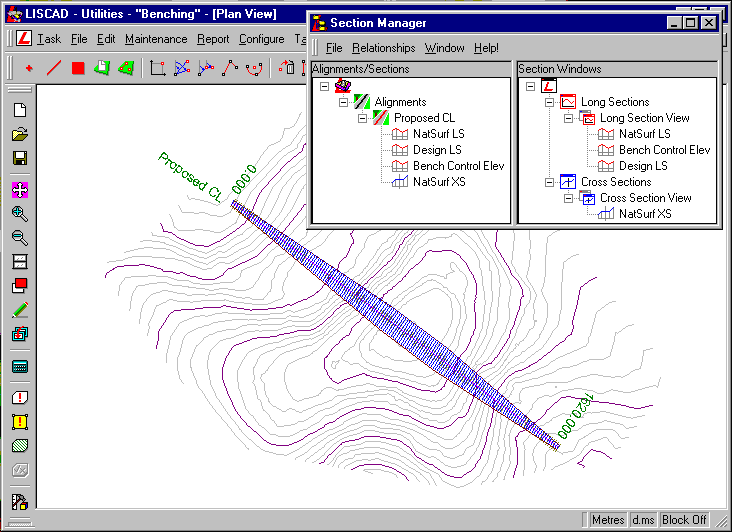
This data set contains a horizontal design control alignment named "Proposed CL". The "Proposed CL" is 1620.000 metres long, has a Corridor of Interest which starts at 20 metres wide, increases to 50 metres wide in the middle section and tapers back to 20 metres wide at the end. A long section profile called "NatSurf LS" has been taken out from the Digital Terrain Model. Section Markers have been constructed every 10 metres and a cross section set called "NatSurf XS" taken out from the model.
- Review Vertical Design
To view the long section window select either Window/Long Section View from the main menu or right click on Long Section View in the Section Windows tree and select Open from the pop-up menu.
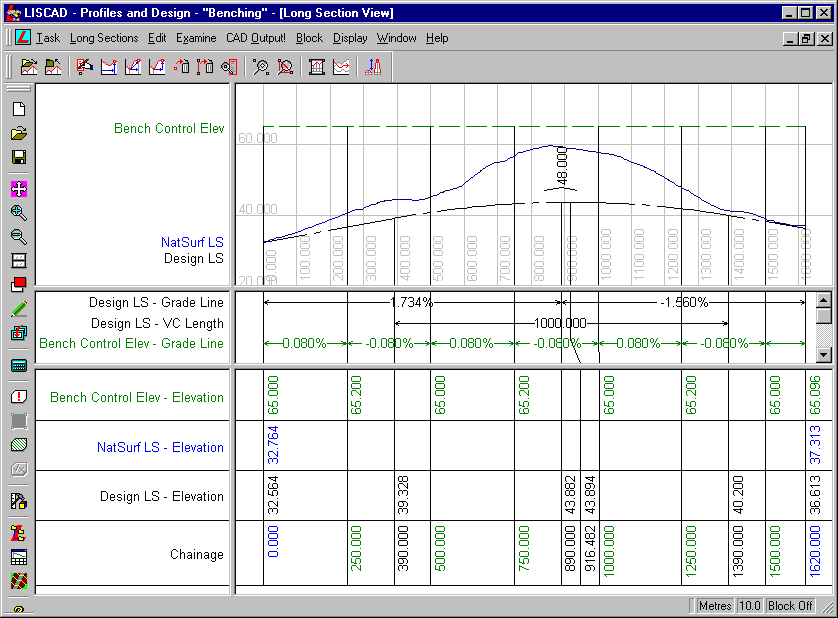
This view shows three long section profiles along the "Proposed CL".
- "NatSurf LS" - Created from the digital terrain model;
- "Design LS" - This is the proposed crown of the road. This has been designed based upon the current natural surface with the intention that the entire design will be in cut;
- "Bench Control Elev" - This is another design which will be used as a control of the elevation and drainage of the benching. This surface will not be part of the final design in its own right. It has a rise and fall of 0.08% over each 250 metre length to ensure that water does not pool on the benches. This design surface will only be used in case 2 where we want to control the elevation of the benches independently of the road surface.
It is only a control surface that will ensure that the benches are created at the desired elevation and that each Along this horizontal alignment a long section profile of the current natural surface named "NatSurf LS" has been created from the Digital Terrain Model. Using the "NatlSurf LS" long section profile as a guide, a vertical design for the road has also been created called "Design LS".
- Review Cross Sections
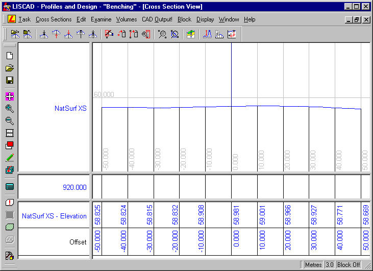
To view the Cross Sections select Window/Cross Section View. This window shows the cross section set "NatSurf XS" which has been generated from the current digital terrain model.
- Case 1 - Creating Benching Based on the Road Elevation
From Utilities/Tables/Template Editor, open the template file "Benching.tle", it contains a single template called "Finished Surface".
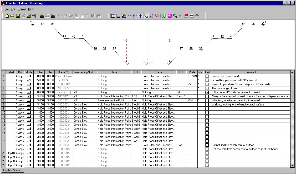
It uses 8 codes:
BENCHTOE - Outside edge of the Bench / Toe of Bank BENCHTOP - Inside edge of the Bench / Top of Bank CROWN - Proposed road crown EOP - Edge of Pavement EOD - Edge of Drain (Outer) ERR - The template encountered an unexpected error condition INV - Invert of an open drain, either along a bench, or at the edge of the road LOW - Limit of Works, the outermost point in the design section. The "Control Elev" in the template represents a surface that is used to calculate elevations for the benching. When the surface matching is performed, it will be matched to the long section profile "Bench Control Elev".
The "NS" in the template represents the existing ground level. When the surface matching is performed, it will match to the cross section set "NatSurf XS"
To assist with understanding the template instructions it is best to break it down into manageable sections
Lines 1 - 4

These instructions produce the basic road and drain profile from the crown of the road to the outer edge of the drain. These instructions are always executed for every section.
Line 5.

This instruction tests to see if the template is in cut. If the template is in fill (or more than 33m cut) this instruction goes to the "Fill" label. As the difference between the design and the natural surface is known to be always in cut and less than 33m it is not necessary to have a "Fill" case. If the design changes a "Fill" case can be added if required.
Line 6.

This instruction is used as a switch, allowing the same template to be used for both Case 1, and Case 2, as described in the aims section of this tutorial.
If the DO field is set to "Always" the benching will be created with the elevation controlled by the road design as described in Case 1 of the Aims Section.
If the DO field on this line is set to "Never" the template will process the instructions required to create the benching using elevations from the "Control Elev" surface, as described in Case 2 of the Aims Section.
Line 7.

This instruction will only be executed if instruction line 6 is set to "Never", which is Case 2.
It performs an initial check to see if benching is required. If not, it will create a conventional batter and go to the "Stop" label.
This is similar to the "Fill" label mentioned under Line 5, this label doesn't exist, and the template will terminate.
Lines 8 - 18

These instructions will only be executed if instruction line 6 is set to "Never", which is case 2.
They probe out 33.1m looking for the "Control Elev" surface in 3.0m steps (except for instruction line 8). The "Control Elev" surface is used to control the drainage.
When probing for the "Control Elev", steps of 3.0m are generally used. The first one however (instruction line 8) is 3.1m. This stops the creation of benches less than 100mm high. The height of the first bench can therefore vary from 0.1m to 3.1m, rather than the 0.0m to 3.0m that is used for subsequent benches.
Note on instruction line 18 that if the "Control Elev" surface cannot be found inside the 33.1m, a point with the ERR code is created.
Lines 19 - 29

These instructions will only be executed if instruction line 6 is set to "Never", which is Case 2.
These instructions reverse the probe back down from the "Control Elev" the required number of 3.0m steps to the starting bench.
Lines 30 - 36

These instructions will only be executed if instruction line 6 is set to "Never", which is Case 2.
These instructions determine elevation of the first bench, so that appropriate coding can be applied. This ensures that the benches are coded based upon their elevation and not with respect to the road.
Lines 37 - 71
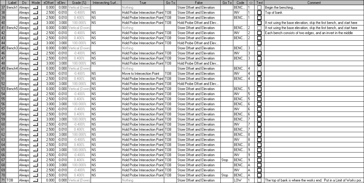
These instructions create the benches and are executed in both Cases 1 and 2.
For each instruction that performs an intersection test with the natural surface, if an intersection is found, the Go To directs it to "TOB" (instruction line 71). This is the only instruction line that creates the actual intersection point. The reason for this is that all intersection points are given the same code "LOW" (Limit of Works). Otherwise if an intersection is not found the point created is given a code relevant to the bench it belongs to.
Minimize the Template Editor without making any changes to the template.
We will now create a Template Implementation Set to generate the design cross section set. The benches in this set will be controlled by the road design surface (The long section profile "Design LS")
Open the Template Implementation dialog.
This can be done through the section manager:
Open the Section Manager (Windows/Section Manager)
Right click on the long section "Design LS" in the left hand (Alignments/Sections) pane, and select "Create Implementation Set..."
It can also be done from the toolbar, or the Profiles & Design/Profile/Template Implementation.
From the Template Implementation dialog, enter the following values:
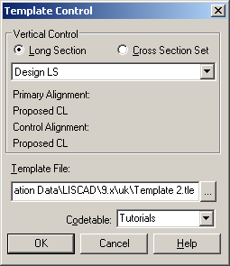
Control Parameters: Select the template "Benching.tle". Confirm that "Design LS" is the control long section, and "Benching" is the code table.
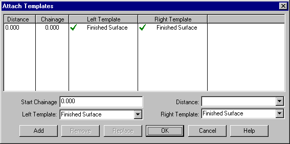
Attach Templates: From a start distance of 0.00, attach "Finished Surface" as both the left and right template.
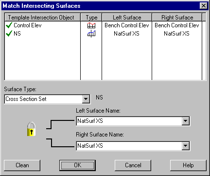
Match Intersecting Surfaces: Match the template surface "Control Elev" to the long section "Bench Control Elev" and "NS" to the cross section set "NatSurf XS". Note that although "Bench Control Elev" is along the central control alignment, it's elevation at any section, can be tested against regardless of the offset from where it occurs.
Modifications: Not required.
Output Parameters: Select a suitable colour and line style. Check the output type is "Design Only".
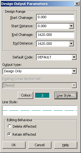
Return to the main Template Implementation control dialog. Enter a Cross Section Set name of "Design XS" and save the Template Implementation Set as "Benching TIS". Select Open Cross Section in: Cross Section View. This will activate the current cross section window and automatically open the "Design XS" set created.
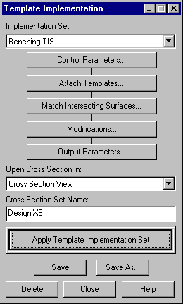
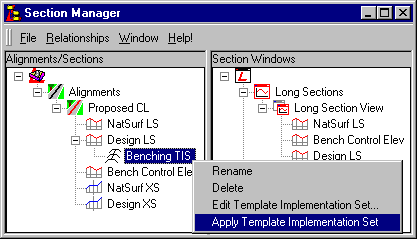
The template implementation set can be applied either by using the "Apply Template Implementation Set" button on the Template Implementation dialog, or by selecting "Apply Template Implementation Set" from the Implementation Set's context (right click) menu in the Section Manager.
Step through the Cross Sections. Benching first appears at a distance of 200.0m.
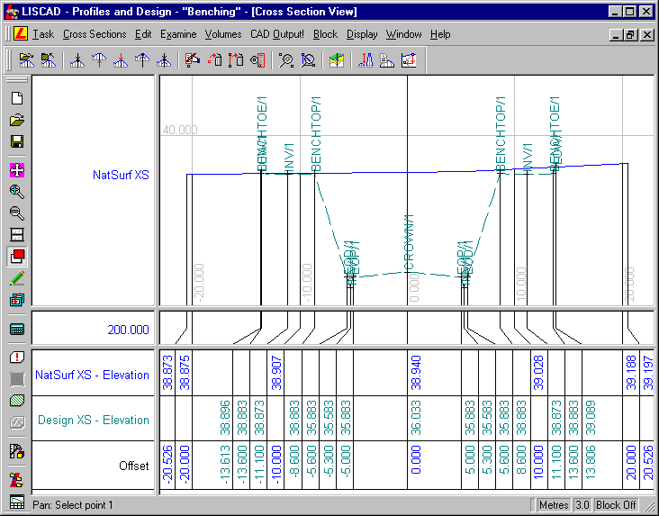
Step through the sections to confirm that the benching has been created using the elevation from the road. Note that the height difference between adjacent Tops and Toes of Bench is always 3.0m, as is the height difference between the Edge of Drain and the first Top of Bench.
- Case 2 - Creating Benching Based on the Bench Control Elevation
Design
Restore the template editor from the bottom left corner of the screen and look at instruction line 6. Change the DO field from "Always" to "Never". This will allow instruction lines 7 to 36, that had been skipped previously, to now be processed. After selecting "Never" from the dropdown list, move the focus out of this control to indicate you have finished editing, and save the template file.
Minimize the Template Editor, and return to the Section Manager. Right click on the "Benching TIS" Implementation Set, and apply it. This will overwrite the existing "Design XS" Cross Section Set, and update it in the displayed views.
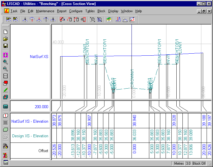
Note that the elevation of the benches have changed. The change in elevation between similarly coded points on the benching, at adjacent sections, is now 8mm. This is because the benching elevations are controlled by the "Bench Control Elev" long section profile, which has grades of plus and minus 0.8%.
- Areas for further investigation.
By changing the "Bench Control Elev" long section profile, and applying the implementation set again, the longitudinal grade of the benches will also change. You can go into the "Long Section View" window, and edit the "Bench Control Elev" long section, and after reapplying the Template Implementation Set, observe the changes in the benching created. Try doing things like changing the location of the low points, and altering the longitudinal grade.
By changing and inserting lines near template instruction lines 38 and 39 in the template and the other similar pairs, the profile of the cut-off drains along the benches can be changed. Try to change the central open drain down the centre of each bench into a box drain, near the inner edge of the bench.
In Section Manager, long sections have a context menu command that allows them to be moved vertically. Using this function to move the "Bench Control Elev" long section profile, reduce the earth works required in the case 2 example.
Conclusion
You have now completed this tutorial and should have an understanding of Templates, and experienced some of the functionality of the Section Manager.
You have also:
- Learnt to use the "Always" and "Never" DO fields in a template to prevent groups of template instructions from being processed;
- An understanding of the use of Probe points, in the template, to search for surfaces;
- Realised the importance of using an appropriately constructed code table, and how to use it with the template editor to highlight unusual happenings;
- Concluded that the templates interpret a Long Section Profile Surface as a horizontal line, much as they treat an Alignment Surface as a vertical line.