Customising drawings containing cadastral plan forms and saving these customised drawings as templates will reduce your plan production time. This tutorial shows you how to create customised templates that you can use when creating a set of cadastral plans.
In this tutorial you will learn how to:
- Configure the printer, layout, and margins for a drawing
- Create a viewport
- Insert a company logo
- Create project attributes
- Insert project attributes as text into drawings
- Copy and paste linked text to other drawings
- Insert instances of blocks
- Save the customised drawings as drawing templates
- Save the customised project as a project template
Once completed, you will understand the difference between:
- Drawings
- Viewports
- Sheet numbers
- Drawing sets
- Drawing numbers
- Drawing templates
50 minutes
CAD Module
Open the Project
- Click
 to access the File menu.
 -
Click Open, then navigate to Documents\Tutorial Data and select Plan Forms.neo.
There are 2 drawing views, a model view and the start page open in the work area. The drawing view tabs are labelled with the name of the drawing.
The drawings include plan forms for creating cadastral plans. The plan forms text and linework were imported from government supplied plan form files in DWG format.
After importing the files:
- Drawing names were edited
- Layer names were edited
- Viewports were added
- Text styles were created
- A block definition was created for a north point
- Blocks were inserted
- Project properties were created
- Linework was joined
- Linked text was inserted so that required text in the plans is pre-filled when values are added for the project attributes
- Some customised drawings have then been saved as drawing templates
You will learn how to finish customising the remaining 2 drawings and save them as drawing templates so they can be used to create new drawings that have the required text and linework. Then you will learn to add drawing templates to drawing sets.
Depending on your locality, you may require different plan forms when you create your drawing templates. First, you will turn on the grid and snap option so you can snap to a grid location.
-
On the ribbon CAD tab, in the Draw group, click
 beside
Grid then click Settings.
- In the Display group, click the Style list, select Dot, then type 10 in the Interval box. Select the On checkbox.
-
In the Snap group, type 1 in the Interval box, the select the On checkbox. Click OK.
The Grid is displayed in the drawing.
The 'Generic Plan (Subsequent) – Landscape' is the active view, so this is the drawing displayed in the work area.
The drawing sheet is shown as white and represents the paper. The print margins are shown as dashed lines.
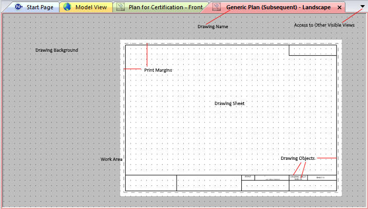
You can draw in any part of the drawing including the background but only objects within the print margins will be printed.
You can change the colour of the Drawing View Sheet and Drawing View Background in Manage Colours.
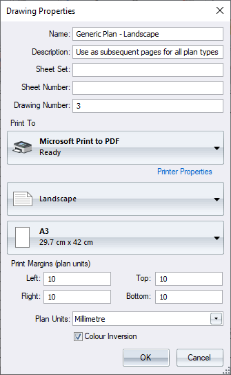
Set the Printer
-
On the ribbon CAD tab, in the Drawing group, click
Properties.
The Drawing Properties for the drawing in the active drawing window displays.
|
|
Create Linework on the Drawing
The linework in your drawings was imported from a DWG file, however, you can also create linework using the draw tools.
- Click the view tab Plan for Certification - Front to display the other drawing window.
- On the ribbon CAD tab, in the Draw group, click the
 beside
 Mode.
-
Click Segment.
In this mode a single line segment will be created each time you click a start and end location for the line. You will add a line to the drawing under the COUNCIL/BODY/PERSON text, in the VESTING OF ROADS AND/OR RESERVES section of the plan form.
- On the ribbon, in the Layer group, click the Active Layer list, then select Plan form minor line.
- On the ribbon, in the Draw group, click
Straight.
-
Right-click the vertex shown with the rubber band below.

- When you have the correct vertex, click to accept your tentative selection.
-
Move the mouse pointer to the right to the next vertical line, then right-click to tentative select a vertex.

- When you have the correct vertex, click to accept your tentative selection.
-
Click
Straight to exit the draw tool.
To exit a draw tool you can either press Esc, re-click the draw tool, click Single or select another tool.
Create a Viewport
A viewport creates a window into the model. You will create a layer for viewports then add a viewport to the 'Generic Plan - Landscape' drawing.
- On the ribbon Home tab in the Tools group, select the Layers checkbox.
- In the Layers tool window, click
to display the layer menu, then select New.
- In the Layer dialog, type Plan form viewports to override the default layer name.
- Click the Display tab.
- Click in the Type list then select viewport from the object list.
-
Click the Colour box then select
 and pick Grey
  (808080) from the colour palette. Click OK.
Any viewport created on this layer will be drawn with a grey border.
The layers visible in the model view at the time a viewport is created will be visible in the viewport. Before creating a viewport consider the layers you will want visible and hidden by default and edit the layers visibility in the Layers tool window to reflect this. - Click the Generic Plan - Landscape drawing.
-
On the ribbon CAD tab, in the Viewport group, click
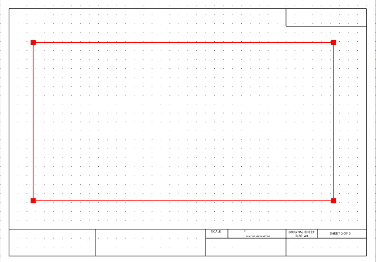
New. On the drawing sheet, click the location of the top left corner of the viewport, then click the location of the bottom right corner as shown in the diagram below.
-
Click
New to exit viewport creation mode. Since there are no objects currently in the model the viewport appears empty.
You can use the Move tool to resize the viewport.
You will now configure the scale of the viewport. A View Scale is the scale used to display all model data in the viewport. Text, images, symbols and line widths in the model, that have been sized using plan units, have an additional Plan Unit Scale applied prior to applying the View Scale.
- On the ribbon Home tab, in the Tools group, select the Attributes checkbox.
- In the Attributes tool window, click Selected Objects to display the viewport properties.
- In the Viewport category, click the View Scale box, then select 1:1000 from the list of commonly used scales.
-
Highlight 500 in the Plan Unit Scale box, then type 1000.
Create a Project Attribute
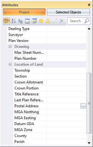
The project has several predefined project attributes whose values can be inserted as text. You will add an additional project attribute that you will use later to add linked text to your drawings.
-
In the Attributes tool window, click Project to display the project attributes that have already been inserted into the project.
- Click
, to display a list of project attributes you can insert into the project.
-
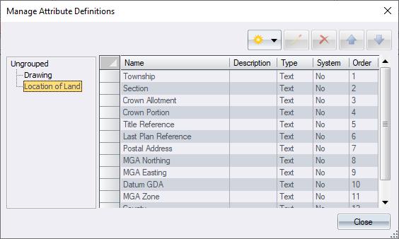
In the left panel click the Location of Land group to add the new attribute to this group of attributes.
- Click
to define a new attribute, then click Text.
-
In the Attribute Definition dialog, type Council in the Name box, then click OK.
On the List tab you could create a list of councils you commonly work in so the attribute value can be selected rather than typed. -
In the Manage Attribute Definitions dialog, click Close.
Now you will insert an instance of this attribute into the project.
-
In the Attributes tool window, in the list of attributes, click the Location of Land group that the Council attribute belongs to.
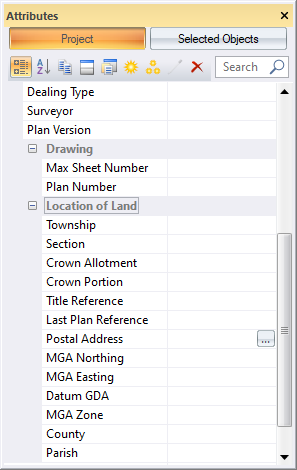
- Click
.
-
In the Create Attribute dialog, click the Attribute list, then select Council (Text).
Since you will create a template from this project, leave the Value box clear as you will add a value for the Council property, each time you create a new project using the project template.
-
Click OK.
Council is added to the list of attributes in the Location of Land group.
Create and Edit Drawing Text
You can insert into a drawing, static text, text linked to project attributes, or text linked to drawing properties. You will edit a text object so that it links to the Council attribute that you just created.
- On the ribbon CAD tab in the Layer group, click the Active Layer list, then select Plan form text.
- Click the Plan for Certification - Front drawing.
-
On the drawing sheet, double click the Council Name: text next to the LOCATION OF LAND section in the plan form.
The Modify Text dialog displays.
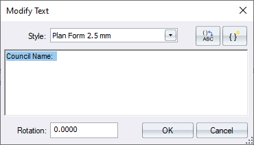
The ‘Council Name:’ text is static text however you will edit the text definition by inserting text linked to the Council project attribute. Plan Form 2.5 mm is a predefined text style created for certain text values.
- Edits to the Plan Form 2.5 mm text style will update all texts that use that text style.
- If <None> is selected for the text Style the active layer text display settings will be used.
-
Click in the blank area of the text box to deselect the 'Council Name:' text and prevent it from being overwritten with the newly inserted attribute, then click
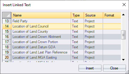
, to display the Insert Linked Text dialog.
A list of all project properties, project attributes, and drawing properties displays. If the project attribute is part of a group like the Council attribute then the attribute name is shown with the group name first and then the attribute name separated by a period.
-
Select Location of Land.Council, then click Insert.
‘Council Name: {Project|Location of Land.Council(Text)}’ displays in the text box.
Click at the end of the text and type City Council.
- Click
. The current value of the text ‘Council Name: City Council’ is displayed. The text linked to the Council attribute is displaying blank since we did not add a value for the attribute when we inserted it as a project attribute.
-
Click OK.

When a value is added for the Council attribute, the value will also display as text next to the 'Council Name:' text.
There are similar text objects linked to project attributes that have been pre-inserted into drawings in this project and will display when project attributes values are added.
If you require different plan forms in your location, you will need to create project attributes and text objects for all of the required text. You will now add a property of the viewport as text.
- Click the Generic Plan - Landscape drawing to make the drawing active.
- On the ribbon CAD tab, in the Draw group click
Text.
- In the Draw Text dialog, click in the text box, then type 1:.
- Click
, then in the Format column select
 for the Scale property.
 - In the Format dialog, click the Round To list, then select 1.
- Click the Truncate list, select None, since truncation is not required when rounding to 1, then click OK.
- Select the Scale property, then click Insert.
-
Click
to display the text value.
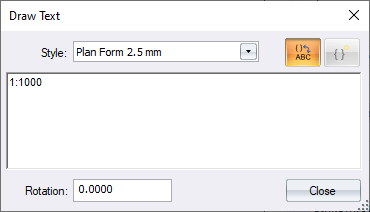
-
Move the mouse pointer to the sheet location at the bottom of the plan form shown below, then click the location for the linked scale text.

The current scale of the viewport is inserted as the text value.
- Click Close.
Copy and Paste Linked Text Objects
You can copy and paste text from one drawing to the next.
- Select the SHEET 3 OF 3 text in the bottom right corner of the drawing sheet, then on the ribbon in the Edit group, click
Copy.
-
Click the Plan for Certification - Front drawing to make the drawing active, then on the ribbon, in the Edit group, click
Paste and move the mouse pointer to insert the sheet number in the location shown below.

The drawing number has changed to 1 since that is the drawing number for this drawing.
You can move the text (or any drawing object) using theMove tool.
- Select the text, then on the ribbon, in the Modify group, click
Move.
-
Click and hold the text then drag the selected text to the desired location.
Since you selected the On checkbox for the Snap settings when you displayed the drawing grid, the text is inserted at an even 1 mm interval from the displayed grid points.
Snap intervals are useful when you want to align objects.
Insert an Image
You will now insert an image of a company logo into the drawing.
- On the ribbon CAD tab in the Layer group, click the Active Layer list, then select Plan form image.
-
On the ribbon, in the Draw group, click
Image, then in the Images dialog, click OK to select the CompanyLogo image.
In the bottom-left corner of the drawing sheet, click the top-left location for the image, then click the bottom-right location to insert the company logo.
- The company logo has been previously added to the project.
- You can rotate or resize the image.
- Images are sized such that the aspect ratio is maintained and the image fits both horizontally and vertically in the defined rectangle.
- If the image has previously been inserted into a CAD drawing, you can pick the image from the Image menu.
-
On the ribbon, in the Select group, click
None to deselect the image.

Insert Blocks
You will now insert predefined North Point and Scale Bar blocks into a drawing.
- On the ribbon CAD tab in the Layer group, click the Active Layer list, then select Plan form blocks.
- Click the Generic Plan - Landscape drawing to make the drawing active.
- On the ribbon, in the Draw group, click the
 beside
 Block, then click Block Definition.
-
In the block definitions dialog, select North Point then click OK.
The North Point displays in the drawing and follows your mouse pointer.
- Click a location for the block somewhere in the top left-hand corner of the drawing sheet.
- On the ribbon, in the Modify group, click
Move, then use the mouse to zoom in on the block so that you can distinguish between corner and middle grip points.
-
Press and hold Ctrl, then click a
 and move the mouse pointer diagonally until the desired size is reached. Click then release Ctrl.
- Pressing the Ctrl key maintains the aspect ratio of the block.
- You can also scale the block and rotate it in the Attributes tool.
While you are still in Move mode, you may need to move the location of the block so that it fits on the drawing sheet and is within the plan form border and the print margins.
-
Click on the block, but away from the grip points, then drag the block to the new location.
When you add values for the project attributes 'MGA Zone' and 'Datum GDA' the blocks text will be updated. You will insert the scale block into the same drawing.
- On the ribbon, in the Draw group, click the
 beside
 Block, then click Block Definition.
- In the block definitions dialog, select Scale Bar then click OK.
-
Place the block in the drawing as shown below.

-
Press E to exit the block insertion tool.
Once you have determined an appropriate scale for displaying model data in the viewport you can add text to the scale bar at each 10mm interval using the ‘Plan form 1.5 mm’ text style. Scales bars and north points have been pre-inserted into the remaining drawings where relevant.
Save As Drawing Templates
Now that you have added commonly used items to the drawings, you will save the drawings as templates so that you can use them as a basis for new drawings.
-
On the ribbon CAD tab, in the Drawing group, click
Templates.
The Manage Drawing Templates dialog displays the existing templates in the project.
-
Click the
 beside
 then select Current Drawing.
A new drawing template named Generic Plan - Landscape is created based on the active drawing.
-
Click Close, right-click the view tab Plan for Certification - Front, then click Add to Templates.
This is an alternative way to add a template.

-
You can click
to configure the selected templates name, printer, orientation, paper size and margins in the same way you configured the drawing properties earlier.
-
To create a new drawing using one of these templates, on the ribbon CAD tab, in the Drawing group, click the
 beside
New, then select the template.
- Click
to display a template in a view and edit it's contents. When you are editing a drawing template
displays in the view tab.
The Abstract of Field Records requires its own numbering system so you will make these drawings part of a sheet set.
-
You can click
- Click in the Sheet Set column for the Abstract Of Field Records – Front template, then type Abstract.
- Click in the Sheet Number column for the Abstract Of Field Records – Front template, then type 1.
- Click in the Sheet Set column for the Abstract Of Field Records template, then type Abstract.
-
Click in the Sheet Number column for the Abstract Of Field Records template, then type 2.

The Abstract of Field Records drawings have pre-inserted linked text that will display the sheet number as the page number.
You gave the ‘Abstract of Field Records – Front’ drawing template a sheet number of 1. This will always be the first page of the sheet set.
The ‘Abstract of Field Records’ drawing template may be used multiple times but will never be the first page, hence the sheet number has been set to start at 2 and will increment from there.
Drawings created from these templates will still have a drawing number which must be unique for all drawings in the project including those in a different sheet set. The drawing number will determine the print order and can also be used for numbering sheets. - Click Close.
Lock Plan Form Layers
Since you will not be making any more changes to the linework in the plan form you will lock the layers containing the linework to prevent lines from being accidentally edited or deleted.
- In the Layers tool window, select the Plan form major line and Plan form minor line layers then click
for one of the selected layers to lock the layers and protect their objects from being edited or deleted.
Remove Drawings
Since this project will be saved as a project template you will now delete the drawings that you have used to create the drawing templates.
- On the ribbon CAD tab, in the Drawing group, click
Views.
-
In the Manage Drawing Views dialog, select both drawings then click
.
- Click
to display an undisplayed drawing in a view.
- You can create new drawings or edit the properties of existing drawings from this dialog.
- Click
- Click Close.
Save as Project Template
You will now compact the project and save the project as a template that will contain all the drawing templates, blocks, texts, text styles, and attributes.
- Click
 to display the File menu.
 - Click Save As Template. The Save As dialog opens in the Templates folder that is configured in the projects General Options.
- Select the Close and compact checkbox.
-
Type Plan Forms Template in the File name box, then click Save.
- When you start a new project this template will be available from the Available Templates list.
- If you already use project templates, you should create the drawing template in these templates or use the Manage Import
tool to import the drawing templates into your project templates.
You have now completed the tutorial and are ready to create your own customised project template that you can use when you create plans. You should now be familiar with drawings, viewports, creating linked text to project attributes, inserting blocks, and saving a drawing as template. You should also understand the difference between a sheet number and a drawing number.
If you have any questions please contact: support@listech.com.
