Configure and save settings within a template so that they are included in new projects based on the template.
You will learn how to configure:
- Colours
- Coordinate systems
- Display precisions
- Display options
- Report options
- Text styles
- Layers
- Attribute definitions
- Lookup tables
- Import and export settings
25 minutes
Leica Survey Module
Create a New Project
Templates are simply projects that are preconfigured with the settings that you would like as defaults when you create a new project.
- Click
 to access the File menu, then click New.
 - In the Available Templates list, select LISTECH – Basic.
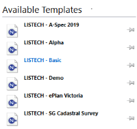
A new project is created. You will customise this project to use as a template for other projects.
Configure the Colours
You will change the model view background colour to white, then select a contrasting colour for the tentative pick colour.
- On the ribbon Manage tab, in the Configuration group, click
Colours.
- In the General category, click in the Model View Background box, then click
 to display the colour palette.
 - Select the colour White (FFFFFF).
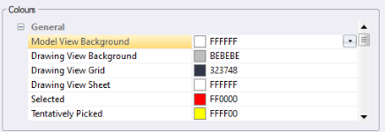
- In the General category, click in the Tentatively Picked box, then click
 to display the colour palette.
 - Select the colour Blue (0000FF), then click OK.
Configure the Coordinate System
You will select the coordinate system you use most frequently and attach a geoid model.
- On the ribbon Manage tab, in the Configuration group, click
Set Coordinate System. The Set Coordinate System dialog displays.
- In the New Coordinate System list, select GDA2020 / MGA Zone 55. The projection and ellipsoid specified for the coordinate system is displayed. Click OK.
- On the ribbon Manage tab, in the Configuration group, click
Coordinate Systems then click Geoid Models.
- In the Manage Geoid Models dialog, click
New.
- In the Geoid Model dialog, click in the Name box and type AusGeoid2020 - Victoria.
- Click in the File Name box, then click
 . Select GEM (*.gem) from the file type list then navigate to Documents\Tutorial Data and select 2020Vic.gem, then click Open.
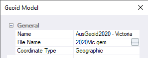
- Click OK, then click Close.
- On the ribbon Manage tab, in the Configuration group, click
Coordinate Systems, then click Coordinate Systems.
- Select GDA2020 / MGA Zone 55, then click
Edit.
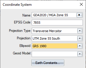
- In the Coordinate System dialog, click in the Geoid Model box, then select AusGeoid2020 - Victoria from the list. Click OK, then click Close.
Configure the Display Options
- On the ribbon Home tab, in the Tools group, select the Options checkbox.
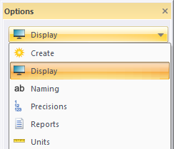
- If the Display page is not currently displayed, click the drop-down menu, then click Display.
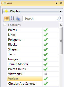
- In the Features category, select the Vertices checkbox to display vertices in the model view.
- In the Labels category, select the Point Names checkbox to display point names in the model view.
Configure the Naming Options
- In the Options tool window, click the drop-down menu, then click Naming.
- In the Polygons category, click the Mandatory checkbox to enforce the entry of a name for every polygon.
Configure the Precision Options
You will set precisions that control the display of values throughout the software.
- In the Options tool window, click the drop-down menu, then click Precisions.
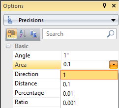
- In the Basic category, click in the Area box, then click
 and select 1.
- In the Basic category, click in the Volume box, then click
 and select 0.1.
Configure the Report Options
- In the Options tool window, click the drop-down menu and select Reports.
- Click in the Header box then click
 .
. - In the Text dialog, type <h2>Your company name<h2>.
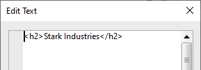
This is the name that will appear at the top of the reports generated by the software. The h2 tags will ensure the company name is displayed using the heading style.
- Click OK, then close the Options tool window.
Create Layers and Attributes
Customise your template to include layers and attributes used by your company.
- On the ribbon Home tab, in the Layer group, click
New.
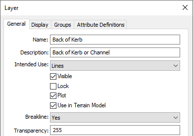
- In the Name box, type Back of Kerb.
- In the Description box, type Back of Kerb or Channel.
- In the Intended Use list, select Lines.
- In the Breakline list, select Yes.
- Click the Display tab.
- In the Type list, select Line.
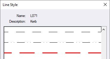
- In the Appearance category, click in the Line Style box then click
 .
. - In the Line Style dialog, scroll down and select the Kerb line (L071), then click OK.
- Click the Attribute Definitions tab.
- Click
, then click Text. The Attribute Definition dialog displays.
- In the Name box, type Kerb Type.
- In the Intended Use list, select Lines, then click OK. Click OK.
You can continue to add layers that you want to appear in projects created from this template.
| Import a code list to automate this process. |
Create a Lookup Table
Create a layer lookup table to map common codes used in the field to layers in the project.
- On the ribbon Manage tab, in the Configuration group, click
Lookup Tables.
- In the Manage Lookup Tables dialog, click
New.
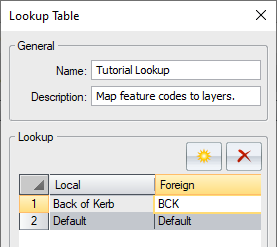
- In the Name box, type Tutorial Lookup.
- In the Description box, type Map feature codes to layers.
A list of the current project layers is displayed in the Local column. The Foreign column lists the feature code or layer that you want mapped to the project layer.
- In the Foreign column, replace ‘Back of Kerb’ with the code ‘BCK’. This is the code or layer that is used when the back of a kerb is measured in the field.
- Click OK then click Close.
| When this lookup table is used, objects with the code or layer ‘BCK’ will be placed on the ‘Back of Kerb’ layer. |
Configure Import Settings
Now that you have created a lookup table, you will configure the import settings so that the lookup table is automatically used when you import a HeXML data file.
- On the ribbon Home tab, in the Data group, click
 below
below Import, then click HeXML.
- Click Options.
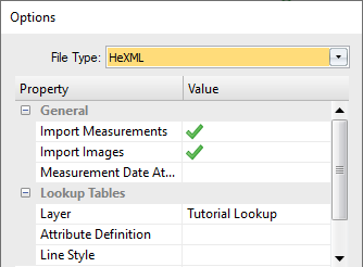
- In the Lookup Tables category, click in the Layer box, then click
 and select Tutorial Lookup from the list. Click OK.
- Click Cancel as you do not need to import a file.
Configure Text Styles
You will customise text styles so that the bearing and distance are grouped together above a straight-line segment. In addition, you will set the rounding required for the text values.
- On the ribbon Manage tab, in the Configuration group, click
, then click Styles.
- In the Manage Text Styles dialog, click in the Type list then select Bearing.
- Click the Straight style, then click
.
- In the Text Style dialog, click the Position tab.
- In the Offset box, type 2.2 to increase the bearing text offset from the line segment.
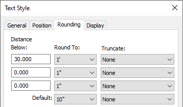
- Click the Rounding tab, to configure the rounding for bearing text to be dependent on the line segment length.
If the line segment distance is less than 30 metres the bearing will be displayed to the nearest minute.
- In the first Distance Below box, type 30. In the first Round To box, select 1’ from the list.
If the line segment distance is longer than 30 metres the default setting will be used.
- In the Default (Round To) box, select 10” from the list, then click OK.
- In the Manage Text Styles dialog, click in the Type list, then select Distance.
- Click the Straight style, then click
Edit.
- In the Text Style dialog, click the Position tab.
- In the Offset box, type 0.75 to group the distance with the bearing text above the line segment.
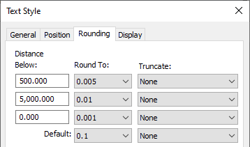
- Click the Rounding tab, to configure the rounding for distance annotations to be dependent on the line segment length.
If the line segment distance is less than 500 metres the distance will be displayed to the nearest 0.005 metre.
- In the first Distance Below box, type 500. In the first Round To box, select 0.005 metres from the list.
If the line segment distance is between 500 and 5000 metres, the distance text will be displayed to the nearest 0.01 metre.
- In the second Distance Below box, type 5000.
- In the second Round To box, select 0.01 metres from the list.
If the line segment distance is greater than 5000 metres the default setting will be used.
- In the Default (Round To) box, select 0.1 from the list, then click OK.
- In the Manage Text Styles dialog, click Close.
Save the Project as a Template
Now that you have configured the project with the settings you want, you will save the project in to the template folder where it can then be used as the basis for new projects.
- To view the folder where the template will be stored, click
 to access the File menu, then click Options.
 - In the Options dialog, click General.
- On the right pane, in the Folders category, the Template box specifies the folder where the software will look for project templates. Click OK.
These settings are for the currently signed-in user and are not unique to the project.
-
Click
 to access the File menu, then click Save As Template.
The File Explorer Save As dialog defaults to the folder specified for Template in your Options settings.
- In the File name box, type Tutorial Template.neo, then click Save.
Use the Template to Create a New Project
Now that the template has been saved to the templates folder it can be used as the basis for new projects.
- Click
 to access the File menu, then click New.
 - Your template will now appear in the Available Templates list.
- Click Tutorial Template and a new project is created that has the same settings as your template.
- Anything that can be saved in a project can be included in a template. In addition to the settings shown in this tutorial, you could configure:
- Report settings
- Units
- Text rules
- Table styles
- Measurement processing options
- Transformations
- Image or feature services
- Layer groups
- Alignment design parameters
- Alignment design standards
- Control code tables.
- Point and line styles.
- Hatches
- Block definitions
- Drawing templates
- Queries
- Any project can be used as a template providing it is stored in the configured Template folder.
- Settings configured in the Options within the File menu are user settings and apply to all projects regardless of the template used by the signed-in user.
You have completed the tutorial and learnt how to create a customised template. You can continue to customise the template to your specific needs by opening and saving the template like you would with any project.
If you have any questions please contact: support@listech.com.
