Create a simple subdivision to become familiar with the controls used in the application.
In this tutorial you will learn how to:- Edit properties in a property grid
- Determine the active control
- Pick objects in the model view to insert a value into a control
- Use tentative pick
- Use the arrow keys to edit a bearing by 90 degrees
- Apply simple mathematical equations in a control
- Key in values in units different to the project units
30 minutes
Solve Module
Prepare the Project
Create a new project and apply settings that you will use in this tutorial.
|
 
|
- Click
 to access the File menu and then click Options. The General page is displayed.
 -
In the User Interface category,
- Select the Informative Mouse Pointers checkbox. This setting will help you determine what action the active control is expecting.
- Click the Tentative Pick box. Click
 and select Right Mouse Button.
 - Click the Label Size box. Click the up arrow of the spin control that appears on the right of the box to increase the size of labels to 10 pixels.

- Click OK to save the changes and close the window.
Create Boundary Points
You will create boundary points for a lot and learn how to add values to controls using different techniques.
- On the ribbon Home tab, in the Tools group, select the Create checkbox. The Create tool window displays.
-
You can choose the type of object to create from the drop-down menu. Click the menu, then click Point.
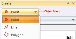
Below the object menu, is a drop-down menu of the methods you can use to create the point. Click the menu, then click Coordinates.
A default value is added to the Name control box, it will automatically increment as you create new points. The Easting box is the active control and this is indicated by the location of the text cursor and the blue border surrounding the box. When a command is selected, the text cursor defaults to the control you are most likely to input values in first.
Type 1000 and press the Tab key to move to the next control.
Now you will use basic arithmetic to enter a value into the controls.
-
In the Northing box type 500+500.
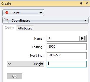
Press the = key to compute the value of the equation.
Some controls allow you to select the type of value you want to enter. The height control is set to Height. The control is expecting you to input an absolute orthometric height.
- In the Height box, type 30∗2, then click OK to create the point.
- In the Create tool window, click Bearing and Distance from the method drop-down menu. Click in the Mode box and select Traverse from the list.
In the From box, type the name 1, then press the Tab key.
The bearing control displayed is dependent on the Direction Type set in the Units page of the Options tool.
Type 23.4532 in the Plane Bearing box and then press the Tab key to move to the next control.
The options in the distance control drop-down list is dependent on the Distance Type set in the Units page of the Options tool.
Click the distance control, then select Grid Distance from the drop-down list. Type 50 in the Grid Distance box, then press the Tab key.
You can insert values in the active control, by picking objects in the model view that share, or can be used to compute, the value you want.
- Click the height control, then select Height from the drop-down list to indidicate that you are inputting an orthometric height. Move the mouse pointer to the Model view. The mouse pointer changes to
to indicate the active control is expecting a value.
- Click point 1 to pick the point and input its height. As there is now sufficient values the point is automatically created.
- On the ribbon Home tab, click
to fit the model view to the two points.
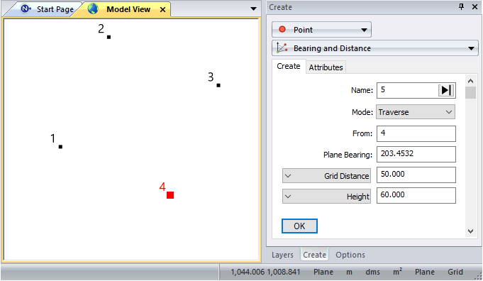
- In the Create tool window, the Plane Bearing control is active. Press the ↑ key to add 90 degrees to the previous bearing. The OK button is enabled as all controls have valid values.
- Click OK to accept the values and create the third boundary point.
- On the ribbon Home tab, click
to fit the model view to the points.
- Press the ↑ key to again increase the bearing by 90 degrees.
-
Press the Tab key to move to the next control.
In some controls, you can enter values in units that are not the project units.
- In the Grid Distance box, type 164.042F to enter the distance in international feet.
- Press the = key to convert the value to the project units.
- Press the Enter key to accept all the values and create the fourth boundary point.
- Press and hold the Alt key and right-click in the Model view. The context menu is displayed which contains previously used commands.
-
Release the Alt key and click
Fit View from the list of commands.
Create Boundary Lines
You will now create boundary lines between the points.
|
Create a Polygon
You will now create a polygon representing the original lot.
|
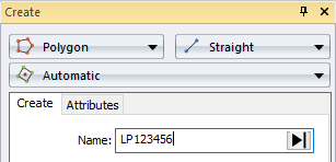 |
- View the Create tool window. You will see a message indicating the polygon has been created.
Subdivide the Lot
You will now subdivide the polygon into 2 equal areas and learn how to input a value into a reference line and bearing control.
- In the Create tool window, click the object drop-down menu, then click Point.
- Click the drop-down menu containing point creation methods and click Number of Segments.
- Type 2 in the Segments box.
- Click the line type control, then select Reference Line from the drop-down list.
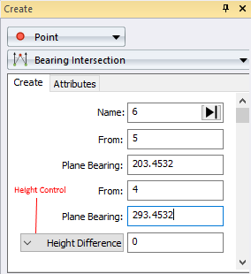
- In the Model view, pick point 2. A rubber band displays from point 2 that follows the mouse pointer. This indicates the control is waiting for another value to define the reference line. '2--' displays in the Reference Line box which also indicates another value is required.
- Pick point 3 to complete the reference line input and create point 5 midway between point 2 and 3. '2--3' displays in the Reference Line box.
|
 |
Now, you will create the lines for the new lots.
- In the Create tool window, click the object drop-down menu, then click Line. The Existing Vertex method remains selected from the previous line creation.
- In the Model view, pick point 5, then 6 and click End.
- Pick point 2, then 5 and click End.
- Pick point 5, then 3 and click End.
- Pick point 1, then 6 and click End.
-
Pick point 6, then 4 and click End.
While points were created in this tutorial to demonstrate how to input values into controls, you can create lines without points.
Create Polygons
You will now create 2 polygons for the new lots using 2 different methods and learn how to tentatively pick an object.
- In the Create tool window, click the object drop-down menu, then click Polygon. The Automatic method remains selected from the previous polygon creation.
- In the Name box type Lot 1.
- In the Model view, click anywhere within the region bound by points 1, 2, 5 and 6 to create the polygon.
On the ribbon Home tab, in the Select group, click
to clear the current selection.
You have seen how to provide input for a control box by picking objects from the model view. Sometimes you may want to inspect the object prior to accepting it as input for a control, or there may be multiple objects in the same location that could provide input to the control. When you create the next polygon, you will learn to use the tentative pick to identify the object that will provide the correct input for the control.
-
On the ribbon Home tab, in the Tools group, select the Attributes checkbox. The Attributes tool window displays. You will use this window to identify the correct objects when you create the polygon. This time, dock the window to the left of the Create tool window.
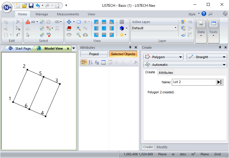
- In the Create tool window, click the drop-down menu containing polygon creation methods, then click Existing Line.
- In the Model view, right-click the line between points 3 and 5 to tentatively pick the line. The line between points 2 and 3 is highlighted in the tentative pick colour.
- In the Attributes tool window the Tentative Object page displays. This is where you can view the attributes of the tentatively picked object. The line is a valid object for creating a polygon and is located where the mouse pointer was placed, however it is not the line we require to create Lot 2.
- In the Model view, right-click the line between point 3 and point 5 again. This time, the line between point 3 and 5 is tentatively picked.
- Left-click anywhere in the Model view to accept the line.
- Pick the line between points 3 and 4. As there is only one line between these two points it is not necessary to tentatively pick this line. The second edge of the polygon is formed.
- Right click the line between points 6 and 4 to tentatively pick the line. The line between points 1 and 4 is tentatively picked.
- Right click the line between points 6 and 4 again. This tentatively picks the required line.
- Left-click anywhere in the Model view to accept the line.
- Click End to close the polygon back onto the original point 5.
Create a Parallel Line
You will now create a line parallel to the line between points 6 and 4 that will represent an easement for Lot 2.
- In the Create tool window, click the object drop-down menu, then click Line.
- Click the drop-down menu containing line creation methods, then click Parallel Line.
-
In the Model view, move the mouse pointer to the location shown by the arrow in the diagram below and tentatively pick the line between points 6 and 4.
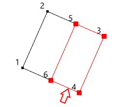
The location of the pick is important as it will determine the direction of the line and allow you to enter the correct offset value.
The tentatively picked line is not the line we require. - In the Model view, tentatively pick the eastern end of line between points 6 and 4 again. This time the required line is tentatively picked.
- Left-click anywhere in the model view to accept the line.
Type 2 in the Offset box.
Because you clicked the eastern end of the line, this defined the line direction as 4 to 6. Entering a positive offset will create a line to the right, which will place your easement inside the polygon.
- Select Height Difference from the height control drop-down list.
- Type 0 in the Height Difference box.
-
Press the Enter key to create the line.
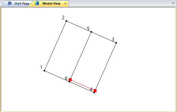
In the process of creating a simple subdivision, you have learnt a variety of ways to input values into controls. In addition you have learnt how to tentative pick an object when there are multiple objects in the same location.
Some things to remember:- Click in a property grid box to edit the value. An arrow on the right of the box indicates you can select values from a list.
- The name of a control may depend on the settings in the Options tool window. For example, the name of the bearing control is determined by the Direction Type settings in the Units page of the Options tool window.
- Some controls, for example the height control, allow you to pick the type of value to enter.
- You can pick an object from the model view to input a value into a control.
- Name controls can be automatically incremented.
- Some controls can work on the current selection.
- Some controls can perform simple arithmetic.
- You can tentatively pick to ensure you are using the correct object.
- When you pick a line for a bearing or reference line control, the location of the mouse pointer is significant.
- You can accept the value and move to the next control, pressing Enter or Tab, clicking in the next control with the mouse, clicking in the Model view to pick an object whose value you want to use in the control, or by clicking OK when all required controls have values.
If you have any questions please contact: support@listech.com.
- When editing properties in a property grid box, click on the far right of the box to automatically display the edit control for the property.
- You can configure the mouse button you use to tentatively select an object and display the context menu in the project options.
 , then select Edges from the list.
 to indicate the active control is expecting a location in the model view. Click anywhere within the square you have just created. The application will check if the location you have selected is bounded by lines and create the polygon.
