Define a symbols dimensions using 2 points and a width and create a point at the centre of the symbol.
- Two points with the same feature code that define the edge of a symbol.
- The width of the symbol.
{1} is the width of the symbol.
Control Code Definition
A control code action Symbol by Edge is given a value '{SymEdg} {1}'.
Measured Points
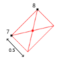
The first point (pt 7) is assigned a code 'TPIT SymEdg 0.5', where 'TPIT' is the feature code for a telecom pit and '0.5' is the width of the pit.
The second point (pt 8) is assigned a code 'TPIT' and is used to define the edge and rotation of the symbol.
- When the codes are processed, an additional point is created at the centre of the symbol on the layer associated with the feature code.
- The symbol drawn for the centre point is determined from the layer of the edge points.
- The Plan Symbol attribute for the two symbol edge points is assigned None.
- You can input the symbols width, in the code or as an attribute, depending on the definition in Edit Control Codes.
