Create a pipe or pipes at a specified depth below the surface.
- At least two points on the surface with the same feature code that belong to a string sequence.
- The depth of the pipes beneath the surface as an attribute of each surface point.
- The diameter of the pipes, for the first surface point in the sequence.
- The location on the pipe or group of pipes to where the depth measurement is made. See the diagram below.
- Multiple rows of pipes where R in the diameter parameter indicates a new row of pipes.
'Attribute Name' is the name of the attribute attached to the surface points that contain the depth value.
{2} is the diameter of all pipes beneath the surface points and the row where they are located.
{3} indicates where on the pipe the depth was measured to. Choose from one of three locations; I (Invert), O (Obvert) or M (Centre).
Control Code Definition
A control code action 'Subsurface Diameter' is given a value '[{0=SubSurfDiam}] Depth [{2:Diameters} {3:Location}]'. Where 'Depth' is the name of an attribute defined on the Water layer.
A control code action 'Join Start' is given a value 'ST'.
Measured Points
If the parameters {2} and {3} are entered as part of the code:
The first point (Point '3') is given a code 'Water ST SubSurfDiam "0.2 0.5 0.8 R 0.7 0.2 0.2" O'. A depth of 0.6 is entered as the value for the 'Depth' attribute.
The second point (Point '4') is given the code 'Water'. A depth of 0.8 is entered as the value for the 'Depth' attribute.
The third point (Point '5') is given the code 'Water'. A depth of 0.9 is entered as the value for the 'Depth' attribute.
If the parameters {2} and {3} are entered as attributes of Leica free codes:
The control code ST is entered as a free code.
The control code SubSurfDiam is entered as a free code with the attribute value 0.2 0.5 0.8 R 0.7 0.2 0.2 for the Diameters attribute and o for the Location attribute.
The next point (Point '3') is given a code 'Water'. A depth of 0.6 is entered as the value for the 'Depth' attribute.
The second point (Point '4') is given the code 'Water'. A depth of 0.8 is entered as the value for the 'Depth' attribute.
The third point (Point '5') is given the code 'Water'. A depth of 0.9 is entered as the value for the 'Depth' attribute.
A line sequence is formed between points 3, 4 and 5 at surface level on the Water layer.
This line is used to create 6 pipes below the surface using the specified depths and diameters.
The diagram below represents a cross section of the pipes at the surface point.
When multiple rows of pipes are detected, the location that the depth is measured to refers to the top (O), middle (M) and bottom (I) of the group of pipes. See the diagram below.
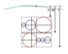
In the diagram, the grey border represents the maximum extents of the group of pipes.
The red circles represent the largest diameter pipe in each row.
It is assumed the centre of all pipes in the same row are aligned vertically.
The group of pipes in each row are centrally aligned with the surface point.
| Error | Description |
|---|---|
| Failed to form a pipe with code Code Name. A Line or Polygon will be formed instead. | The pipes could not be intersected without overlap. This could be due to:
|
- The string on the surface used to create the subsurface line is retained.
- Pipes are placed on the same layer as the surface points.
- The depth must be specified using an attribute attached to the surface point. Define a depth attribute for each layer that subsurface pipes will be placed.
- Use an attribute of type text if multiple pipe diameters are specified using an attribute.
- Surround the diameter parameter with quotation marks if multiple pipe diameters are specified within the code.
- The elevation of the sub surface line is the depth to the middle of the pipe.
- Where multiple pipe diameters are specified the elevation of the subsurface lines is determined for the middle of the largest diameter pipe in the row.
- Where multiple pipe diameters are specified the measured point on the surface is considered to be above the middle of the group of pipes. See the diagram above.
- Where multiple rows of pipes are specified the depth is considered to the top(O), middle(M) or bottom(I) of the group of pipes. See the diagram above.
- In the control code definition, you can define alternate names for the parameter {3} in the form {3:Attribute name (Invert Location name=I,Obvert Location name=O,Middle Location name=M) }
- If alternate values for parameter {3} are not defined the values I, O or M are expected either in a measurement code or within an attribute of type text.
- You can input the location and pipe diameters, in the code or as an attribute, depending on the definition in Edit Control Codes.
- The attributes from the first point in the line are copied to the created shape(pipe) object, hence the copied depth attribute is the measured depth value from the first surface point.
