To complete this tutorial you will require the Profiles & Design, Modelling and Volumes modules.
Aim
The aim of this tutorial is to Transfer a set of Design Cross Sections back into the co-ordinate data base which will then be able to be viewed in the Plan Window. This design can then be used to form an integrated Digital Terrain Model with the existing surface.
Before you begin
Select this button to install the required data files.
- Transfer the Design Cross Sections into the Plan View
Select File/Open and open the file called "Cross Sections Into Plan.see" in the Tutorial folder.
The Transfer Cross Sections into Plan command allows a cross section set to be transferred into the plan view of the data base by creating new points and lines as requested, with the cross section elevations being applied to the points.
Open the Cross Section View by selecting Window/Cross Section View from the main menu.
Select Display/Features and select the cross section set "Original XS". Turn off the Point Attributes: Description. Now select the cross section set "Final Design Surface" and turn on the Point Attributes: Code. Press OK to accept the changes.
You should now be able to see the Codes and String numbers which were set up in the template against each point in the design. For information on setting up the template that generated this design refer to the tutorial "Using the Template Editor". (If the codes are overwriting use the Display/Window or Zoom In commands to get a closer look.)
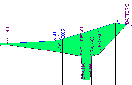
The code is used to define the attributes of the points and lines that are generated in the co-ordinate data base. The string number is used to create string lines between the cross sections. These lines will be generated by matching the code, the string identifier and the points with an offset value closest to each other.
We will now transfer these design sections into the plan view.
Select Cross Sections / Transfer Cross Sections to Plan;
Important: Select the Cross Section Set "Final Design Surface".
The Start and End Chainages should default to the full extent of the control alignment.
Set the Starting Point Identifier to "10000". Note: Be careful to set this correctly to avoid conflicts with existing point identifiers in the data set.
Select the Default Point Code DEFAULT from the drop-down list.
This is the code that will be used for points in the cross sections that do not already have codes associated with them. If [None] is selected then only points in the cross section that have codes associated with them will be transferred into plan. (In this data set all our cross section points have been coded so setting this code is not strictly necessary.)
Turn off the Create Lines Across Sections check box. Setting this joins every point in each cross section with its neighbour to form a string. Normally this is only necessary if sections are close together and points in each cross section are relatively far apart. In this situation creating a string across the sections will help control the digital terrain model formation by preventing triangles being formed that jump across a section.
Check the Create Bounding Lines and set the Bounding Line Code to BATTER. This will ensure that there is a continuous line right around the extents of the design being put into plan.
Check the Create Bounding Polygon and set the Polygon Code to "DEFAULT". This will enable the existing data to be clipped at the polygon and disabled beneath the design so that we can model the combined data without having to delete the existing surface information.
Make sure that all the check boxes in the Management of Existing Objects group box are checked on. This will ensure that all existing features are clipped and disabled, including objects on the Groups which are not currently displayed.
Do not select Allow Lines Between Cross Sections to Cross the Primary Alignment. This prevents the string lines from crossing the primary alignment when the same template has been applied to both sides of the design.
IMPORTANT: All the codes used in the cross sections which are being put into plan and in this dialog box should reference new "Design" Groups that are not used by any other objects currently in the data base. This will keep all the new design information separate from the existing data.
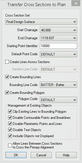
Select OK to validate the data entry fields and transfer the cross sections into the plan view.
After processing the data the dialog box will close.
Note: On slower computers you may experience a short delay as there is a great deal of processing that has to be undertaken to create the new points, lines and polygon, clip all the existing objects and disable them.
- Form a Digital Terrain Model that Integrates the Design Surface
Select Window/Plan View to see the results.
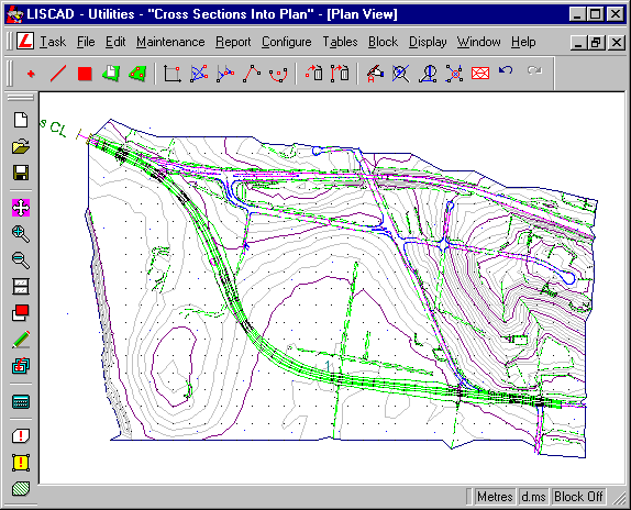
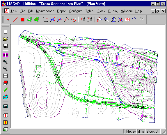
If you zoom in on the design you will notice that all the lines crossing the design area have now been clipped and integrated into the new string lines that have been created. Also there is no sign of the existing lines and points within the design area as this information has all been disabled.
Select Display/Groups to see what Groups are currently active. You will notice that new Groups have been created. These Groups contain all the new information that has been created in the co-ordinate data base, keeping it totally separate from the existing data.
Turn off the following Groups - CONSTRUCTION OBJECTS, CONTROL, HORIZONTAL DESIGN and VERTICAL DESIGN:
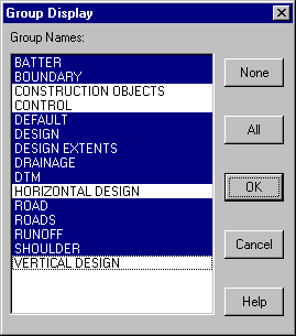
The next step is to create a new model that integrates the design with the existing terrain.
Before creating the model we need to validate the data. Select Task/Terrain Modelling then Modelling/Validation.
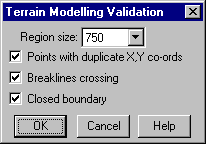
Press OK and it should not report any errors. This verifies that all the existing strings have been successfully clipped and integrated into the design so that there are no crossing breaklines.
Now select Modelling/ Form Model. Select Model No. 2 and give the model the description "Design Model". Press OK.
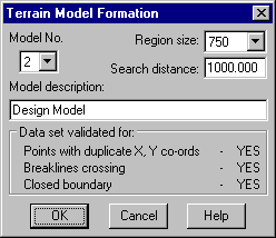
Select Display/Redraw to view the new contour formation.
- Compute Surface to Surface Volumes Between the Original Surface and
the Design Surface
Now that we have a before and after model we will compute a Surface To Surface volume to determine the resultant balance of cut or fill associated with this design.
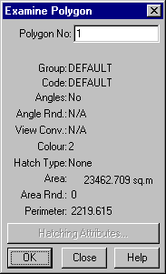
When the cross sections were transferred to plan we asked to create a bounding polygon around the design. To determine the area of the design select Task/Computations/Examine/Attributes/Polygon. Now snap into the design area and the polygon surrounding the design should highlight. Make a note of the area.
Now select Task/Volumes.
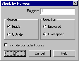
Rather than compute the volume of the entire model we are only interested in the area that has changed, which is confined to the polygon. To achieve this we must make a Block from this polygon. Select Block/Polygon and snap and accept into the polygon. Set the Region as Inside and the Condition as Overlapped. We select overlapped, as the triangles of the original model will overlap the design polygon and we want to make sure that they are all picked up as well.
Press OK to activate the Polygon Block.
Select Volumes/Surface to Surface and set the From Surface as Model 1 "Natural Surface" and the To Surface as Model 2 "Design Model".
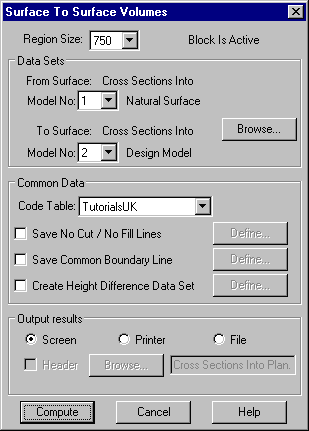
Press Compute to display the following report.
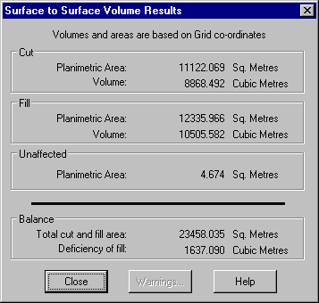
The area is the sum of all the planimetric areas. I.e. Cut (11120.343) + Fill (12337.701) + Unaffected (4.665) = 23462.709m2, which agrees with the area of the polygon that we examined. The volume is showing us an overall deficiency of fill of 1637.090m3.
- Compute a Check Volume Using End Areas
As a further check we will compute the volume by end areas.
Return to the Cross Section View by selecting Window/Cross Section View.
First select Volumes/Define End Areas to make sure that the surfaces are selected correctly as defined below and then press OK.
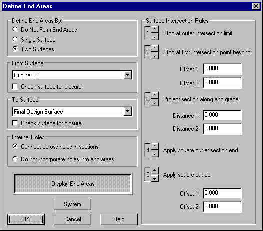
To confirm that the end areas are being defined correctly you can step through the sections and visually inspect them using the Display Sections functions.
Now select Volumes/Volumes by End Areas. By default it should select the complete set of cross sections.
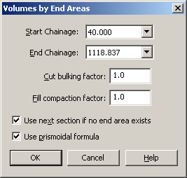
Press OK to view the end area volume report.
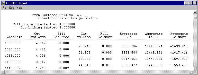
The end area volume gives a deficiency of fill of 1553.459m3, which is a difference of 81.602m3 from the surface to surface volumes. When this difference is taken into consideration against the entire volume for the design, which is cut (8892.477) + fill (10445.936) = 19338.413m3. The difference between the two computations is in the order of 0.4%.
Of the two volume computations the Surface to Surface volumes is the more rigorous. End area volumes has to make generalisations between the sections when it is not certain what is going on. In some sections the spacing between cross sections is 20m. If this interval was reduced the end area volumes will tend to converge on the surface to surface volumes.
Conclusion
You have now completed this tutorial and should have a good understanding of how to:
- Transfer a cross section set into the Plan window
- Form an integrated design model
- Determine the area of the design extents
- Compute a surface to surface volume using a polygon block
- Compute an end area volume as a check.