To complete this tutorial you will require the Profiles
& Design module.
Note: This tutorial cannot be completed using LISCAD Lite.
The information in this tutorial builds upon the ideas and concepts presented in the tutorials "Using the Template Editor" and "Template Implementation". Please ensure you are familiar with these before continuing.
Aim
The aim of this tutorial is to demonstrate how to design a T intersection along two existing alignments. It will also show:
- Design considerations based upon long section information;
- Applying an existing template implementation to cross sections;
- Designing arcs to join existing alignments;
- Two road alignments have been designed, which will meet at a T intersection. The aim is to create the kerb design and surface model for this T intersection. The roads are 6 metres wide.
Before you begin
Select this button to install the required data files.
- Review the Example Data Set
Select File/Open and open the data file "Intersection Design.see".
Select Window/Section Manager to view the alignments and sections currently in the data file.
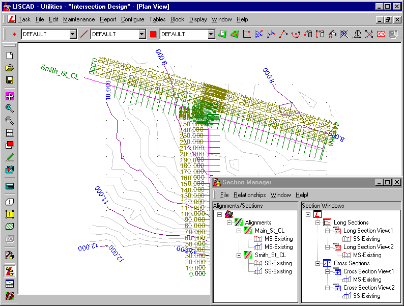
The alignments:
- Primary alignments called "Main_St_CL" and "Smith_St_CL" have been created.
- Long and cross sections of the natural surface, called "MS-Existing" and "SS-Existing" for both long sections and cross sections, were created from the primary alignment.
Corridor of interest and section markers:
- A 40m wide corridor of interest is attached to each of the primary alignments.
- Section markers have been created along the primary alignments, initially at 10 metre spacing, then around the proposed intersection, increased to 2 metre spacing. Additional section markers have been added here, to provide extra cross sections in these areas.
- Create a Long Section Design Along Smith Street
We need to design the street long sections, using the following constraints:
- The ends need to match the existing surface.
- The minimum grade anywhere along the design long section is 0.5%
- The difference between cut/fill amounts in each street should be kept at a minimum at the alignment intersection.
Select Window/Long Section View:1 to view the Long Section for the natural surface long section along the Smith Street alignment.
Place the cursor in the Long Section window and right mouse click, from the pop-up menu select Vertical Exaggeration. Set the Vertical Exaggeration to 20.0.
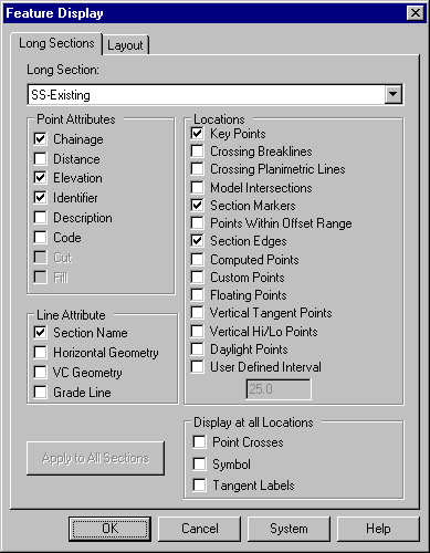
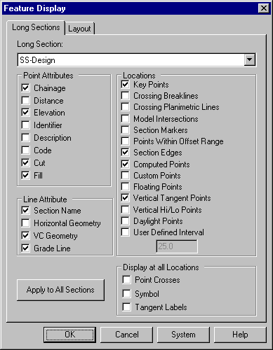
Now right click in the Long Section window again and select Display Features from the pop up menu.
Set the following attributes.
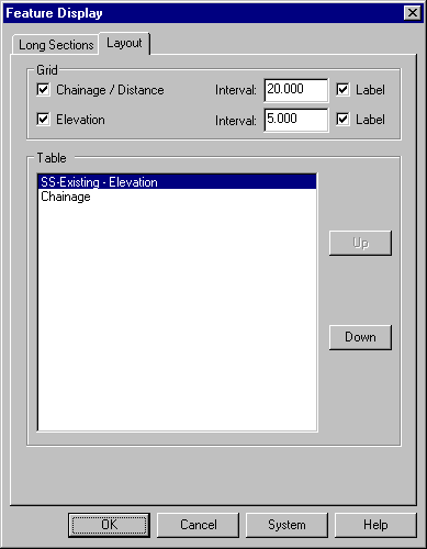
Now select the Layout tab and set the following attributes.
Click OK
Select Long Sections/Create Horizontal Long Section/By Alignment. Enter the Long Section name as "SS-Design"
Make the settings as shown below. Then select OK.
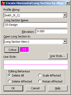
A new Long section has been created in the same window.
Now right click in the Long Section window again and select Display Features from the pop up menu.
For the long section "SS-Design" set the following attributes
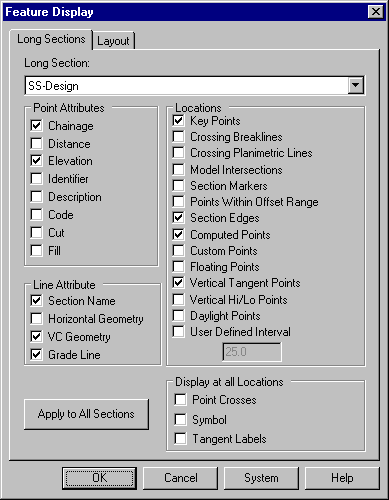
Click OK.
Select Display/Fit to display the full extents of the long sections as seen below.
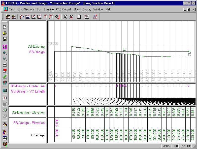
Next use Display/Window (or the Window tool) to obtain a closer view of the area around Chainage 0 to Chainage 60. You will notice that the "SS-Design" section starts at 0.000 whereas the "SS-Existing" starts at 55.030. This is because the "SS-Design" has been created along the full length of the "Smith_St_CL" alignment and the "SS-Existing" has been generated from the digital terrain model and the first point in the alignment is outside the model.
To make the vertical design meet the natural surface we will move the design to the existing surface.
Select from the menu Edit/Move Point/Freehand. Snap and accept the first point on the "SS-Design" line (Pink) at Chainage 0.000, Elevation 9.000 and then snap to and accept the first point on the "SS-Existing" line (Green) at Chainage 55.030, Elevation 9.816. This will move the start of the design long section on to the start of the existing surface long section.
A similar process needs to be completed at the end of the Long Section. Therefore use the Display/Zoom, Fit, Pan or Window tools to obtain a closer view of the area around the end of the Long Section. If you wish to be able to see the points that are in the sections, so that you can be sure you are moving the correct point, select Display/Features and for both sections turn on Display Point Crosses in the Display at all Locations section and press OK.
To cancel out of the Move Point Freehand command you can either press the Esc key or just select the next function you want to use.
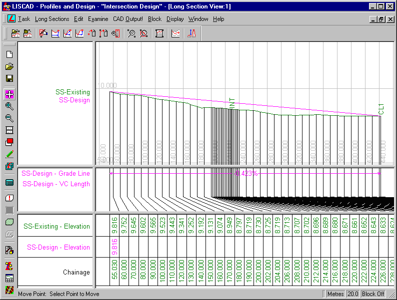
Notice now that the Grade Line of the design long section is 0.423%, which defies the constraint that the minimum grade must be 0.5%.
Select Edit/Create Point/By Chainage & Elevation
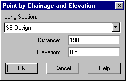
Select the "SS-Design" long section and create the following points:
- Ch. 190.000, Elev. 8.5
- Ch. 320.000, Elev. 7.5
Now we will commence the Vertical Parabola Design. Select Edit/ Vertical Parabola Designer. This LISCAD feature allows Vertical Parabolic Curves to be Created, Examined, Edited and Deleted within Long Sections.
Now Select the Design Parameters button.
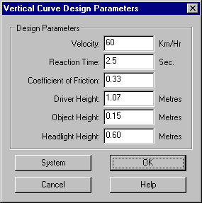
Enter the Design Parameters as displayed. Select OK when completed.
Snap to the Point at Ch. 190.00 in the "SS-Design". Now enter the desired parabolic curve length of 200.
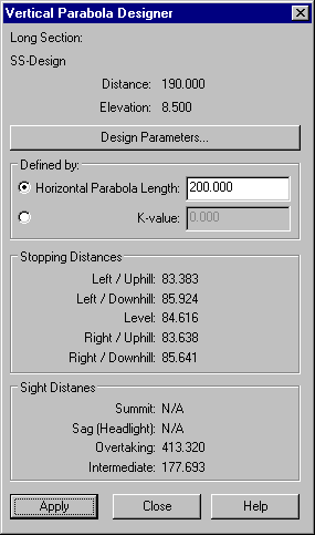
Notice that the Summit and Sag distances have been updated.
Next select the Apply button.
The sight distances are all much greater than the stopping distance making this vertical parabola satisfactory.
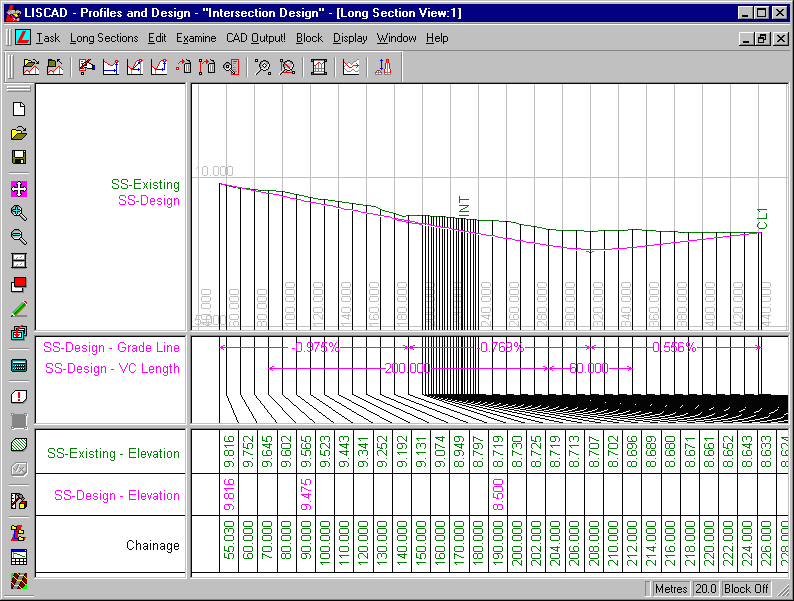
Place a vertical parabola of length 60.000 at the Point at chainage CH 320.000.
Select Close when finished.
Select Display/Base Long Sections
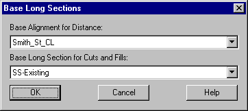
Ensure the above is selected and click OK.
Select Display/Features.
For "SS-Design", ensure the Cut and Fill boxes are checked, and for "SS-Existing", ensure the Section Markers box is unchecked and the other boxes are checked or unchecked as below...
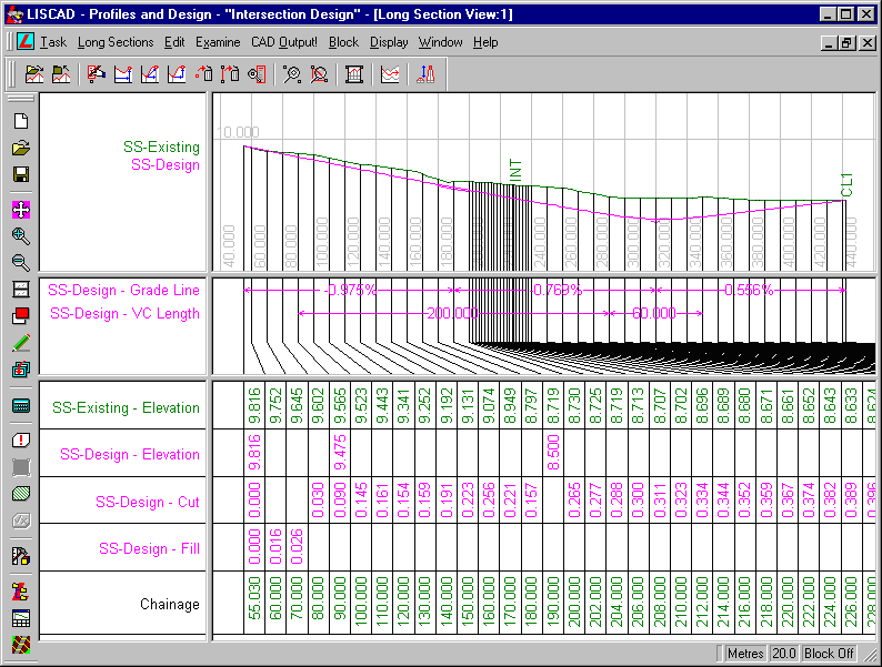
This shows us that Smith Street has a cut of 0.399 at the Intersection. We now need to create a Main Street design long section which will give us a similar value at the intersection.
- Create a Long Section Design Along Main Street
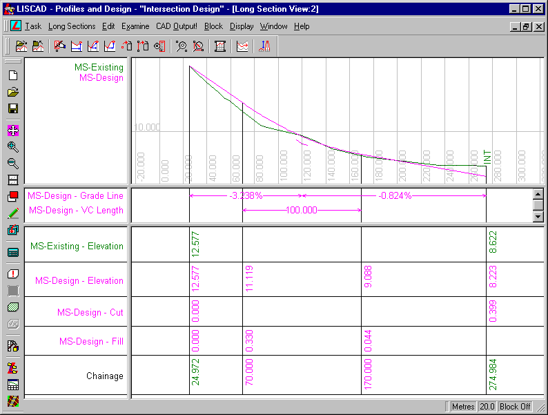
In a similar manner to what you have done for the Smith Street design repeat the above steps for the Main Street alignment, in Long Section View:2 using the following data.
Create a design long section called "MS-Design" at an elevation of 10 metres.
For the "MS-Design" long section, move the design end points to the existing end points and create the following point:
Ch. 120.000, Elev. 9.5
Adjust the vertical exaggeration if desired.
Create a vertical curve at that point with a length of 100 metres.
Now select the last point on the "MS-Design" alignment, in other words at the intersection, which should be at an elevation of 8.622, after moving the design end points to existing end points, and using Edit/Move Point/Relative, move the point vertically down by 0.399 metres.
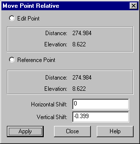
Doing this will thereby ensure that the same cut value for the Main Street alignment applies at the intersection, as it does for Smith Street.
- Create Design Cross Sections Along Both Streets
Now we have the design long sections for each Street, it is now time to design the design cross sections, using the template file, "Intersection Design.tle".
Open this file in the Template Editor, using Tasks/Utilities/Tables/Template Editor.
Note there are two tabs along the bottom of the editor window, indicating that this file contains two different templates, called "Road" and "Kerb".
These templates use 4 codes:
- LIP - The design lip of kerb
- INV - The design channel invert
- BOK - The design back of kerb
- BAT - The design batter
We will start by examining the template "Road".
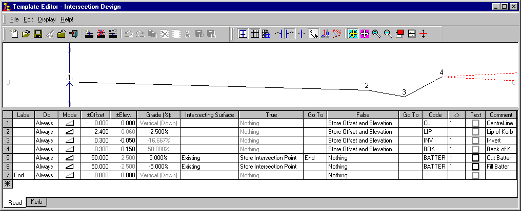
For an explanation of what these lines refer to, refer to the Template tutorial which was a pre-requisite for this tutorial.
The "Existing" Intersecting Surface is the natural or original surface. This is represented in the data file by the "SS-Existing" or "MS-Existing" cross section set.
The other template in the file is called "Kerb".
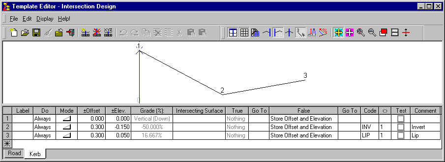
After reviewing the templates we will be using, close the Template Editor and open the Section Manager.
We will now create a Template Implementation Set for the road surface design.
Select the "MS-Design" long section from the Alignments/Sections tree and create a Template Implementation Set for it, using File/Create Template Implementation Set.
Press the following buttons on the Template Implementation Set dialog to set up the required parameters.
Control Parameters:
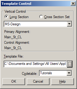
Use the Browse button to select the "IntersectionDesign.tle" template file and set the code table "Tutorials".
Attach Templates:
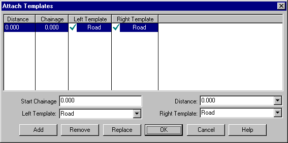
Enter a Start Distance of 0.000, set the Left and Right templates to "Road" and press Add to attach the "Road" template to both sides of the alignment.
Match Intersecting Surfaces:
The Template Intersection Surface "Existing" is in this case matched to the "MS-Existing" Cross Section Set.
Output Parameters:
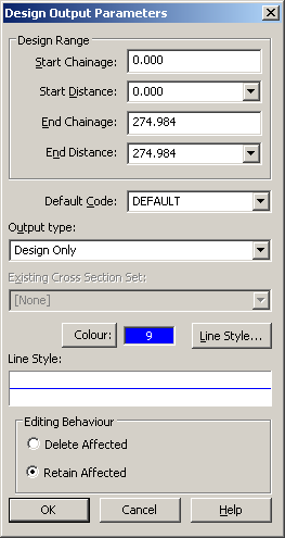
Set the Default Code to DEFAULT, select a suitable colour and line style and check the output type is "Design Only".
In the main template implementation dialog:
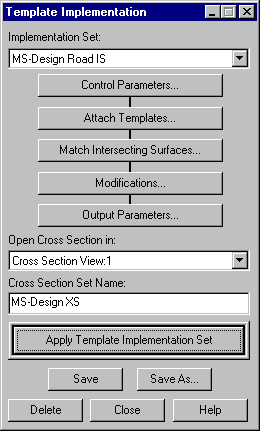
Set "Open Cross Section in" to "Cross Section View:1".
Press Save to save the Implementation Set as "MS-Design Road IS".
Select Apply Template Implementation Set to create the "MS-Design XS" cross section set.
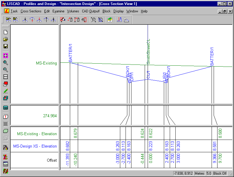
In the Display Features dialog, for the "MS-Design XS" check on Template locations and the Section name line attribute and check on Code point attributes.
You might like to apply a Vertical Exaggeration of 5.0 or more.
Step up and down the cross sections, and confirm that the road has been created as required, and the batters have intersected with the existing surface.
Go back to Section Manager and create and apply a template implementation set for the "SS-Design" long section, using a similar procedure as before, using the "Road" template. Call the Cross Section Set "SS-Design XS", and the Implementation Set "SS-Design Road IS". Open the Cross Section Set in Cross Section View:2 this time.
The Cross Section at the Section Marker of 228.54 is the cross section at the Intersection itself.
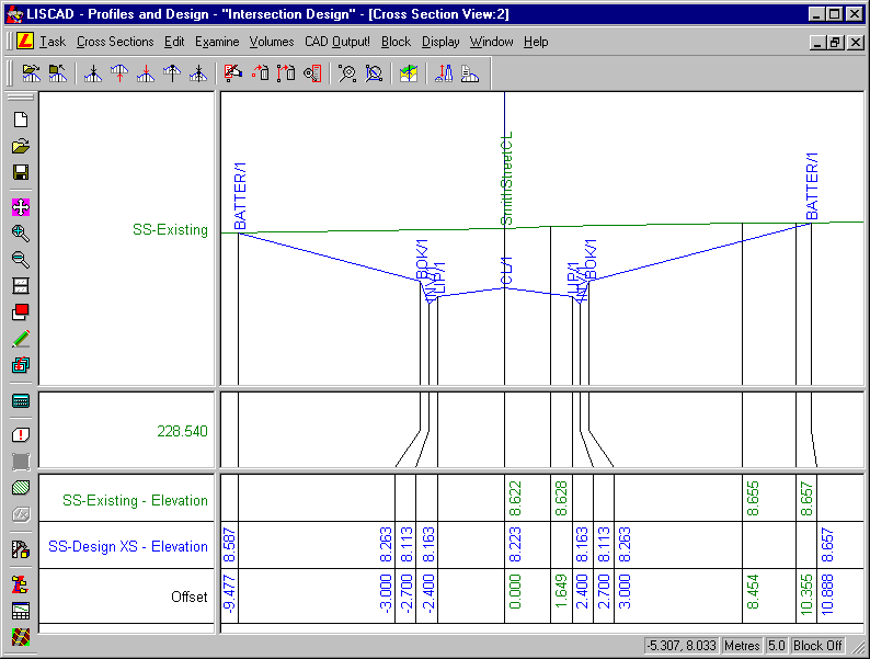
We can now transfer these cross sections to plan.
- Transfer the Design Cross Sections into Plan
In Plan View, select Task/Profiles and Design/Profile/Transfer Cross Sections to Plan.
For the "MS-Design XS" set, set the Start ID to MS1, and for the "SS-Design XS" set, set the Start ID to SS1. For example, here is the Dialog for the MS set.
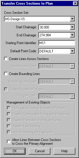
Note that although the Default Point Code is set as DEFAULT, each point created by the Template set should already have codes assigned to them, so this DEFAULT code should not be used if everything has been set correctly.
Transfer both sections to plan.
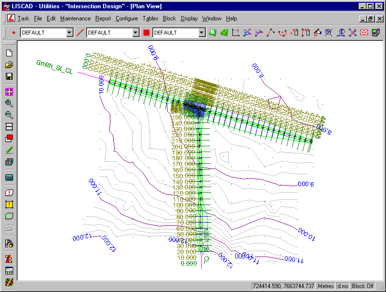
Select Display/Groups and turn off all groups except BATTER, which refers to line where the batter slope intersects the natural surface.
For now, we have finished with the cross section plans lines, so in Display/Features ensure that nothing in the Sections tab is highlighted and in the Alignments tab ensure that the box Always Display Section Markers is not checked. Also go to the Points tab and turn on crosses so that you can easily see the points that have been created and go to the Model tab and turn off contours.
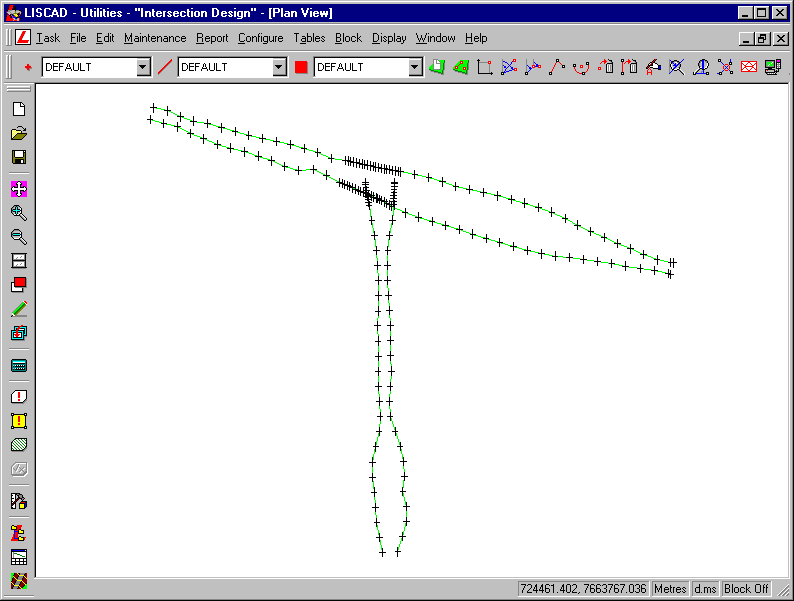
Use the Window tool to zoom in on the area around the intersection.
- Clean-up the Intersection Batters
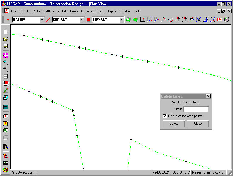
We now need to create the kerbs around the intersection, but first we must delete the BATTER lines that protrude into the intersection. To do this, we need to break the BATTER lines and delete the protruding segments.
Set the Point Code to BATTER.
Select the Task/Computations/Create/Point and Method/Line-Line Intersection
Snap and accept the BATTER lines that intersect.
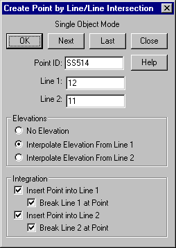
Note that we have an integration tool that automatically allows us to insert points and break the lines at those points. Ensure that these boxes are selected, and the created Point has an elevation interpolated from one of the Lines.
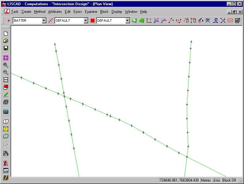
Now the lines have been broken, we can delete the line segments protruding using the Edit/Delete/Lines tool. You can check the delete associated points box too. Snap and Accept the three line segments to delete them.
- Clean-up and Join the Backs of Kerbs
Now we need to create the arcs that will define the kerbs.
Use Display/Groups to turn on only the BOK (back of kerb) group.
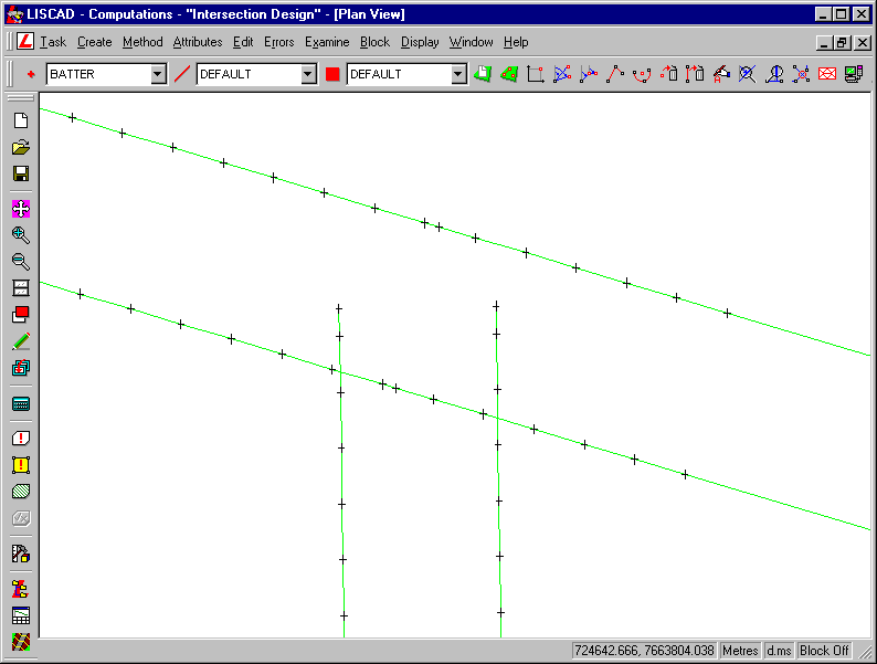
We will create the arcs by Tangent and IP. Select Create/Arc using Method/Tangent and IP.
Ensure that the code for both Points and Lines is set to BOK.
Snap and accept the lines and enter a radius of 6 metres.
Ensure that Interpolate Elevations is checked.
Click Compute to see the arc that would be created.
Click Accept to accept the arc if it looks reasonable.
As a tip, if you turn the Point Identifiers on and Compute the arc, then make note of between which points the suggested arc hits the lines, then edit the Reference Points field to ensure that these line segments are input, the Fillet Line check box will do its job and fillet those line segments out. This will make it easier to delete the rest of the line segments later on in the tutorial.
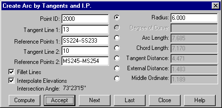
Repeat this to create both arcs.
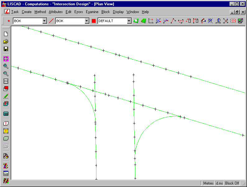
Again, we now need to clean up the BOK lines that protrude into the intersection. Again we need to delete the lines and points as we did with the BATTER lines previously.
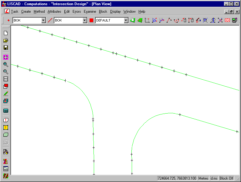
- Clean-up the Inverts and Lips of Kerbs
Turn all the groups back on again.
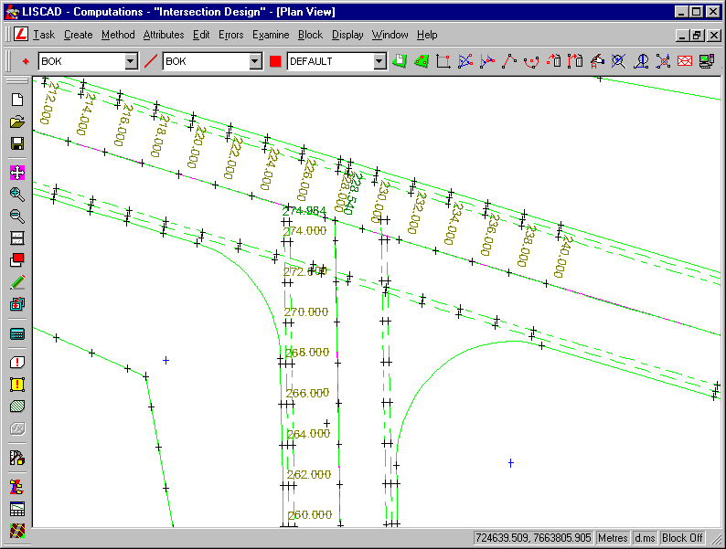
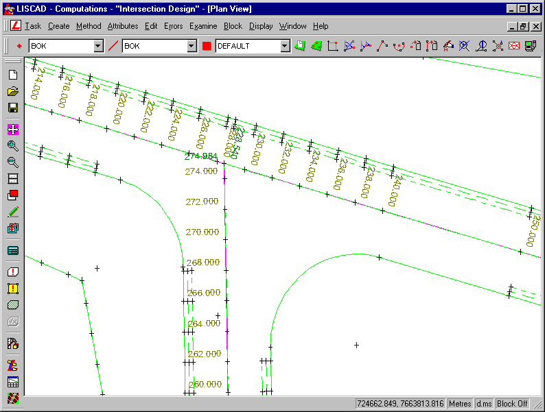
We can see that the INV and LIP lines still protrude into the intersection. Delete those points inside the intersection.
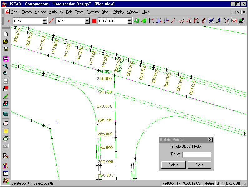
We also need to break the INV and LIP lines along Smith Street, as they are straddling the intersection.
- Create Alignments Around the Back of Kerbs
To create the kerbing, we need to create a new alignment along the BOK. Use Display/Groups to ensure that only this group is on.
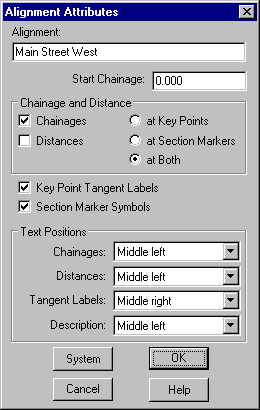
Before we create the alignment, ensure that the distance attribute of an alignment is shown by checking the Distance box in the Attributes/Alignments dialog.
Enter the new alignment name as "Main Street West".
Select Task/Computations then Create/Alignment, Method/Trace. Ensure the Trace in Both Directions box is checked.
Zoom out to see all the BOK lines and click as shown here, selecting the start of Line 9 at its southern-most point.
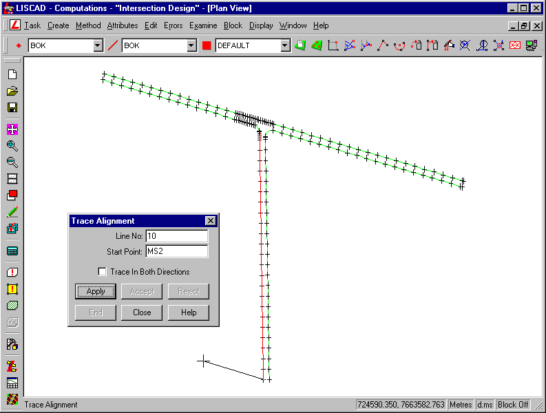
Click Apply.
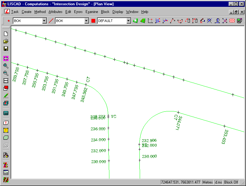
This will create an alignment along the west side of Main Street, round the arc and along the south side of Smith Street.
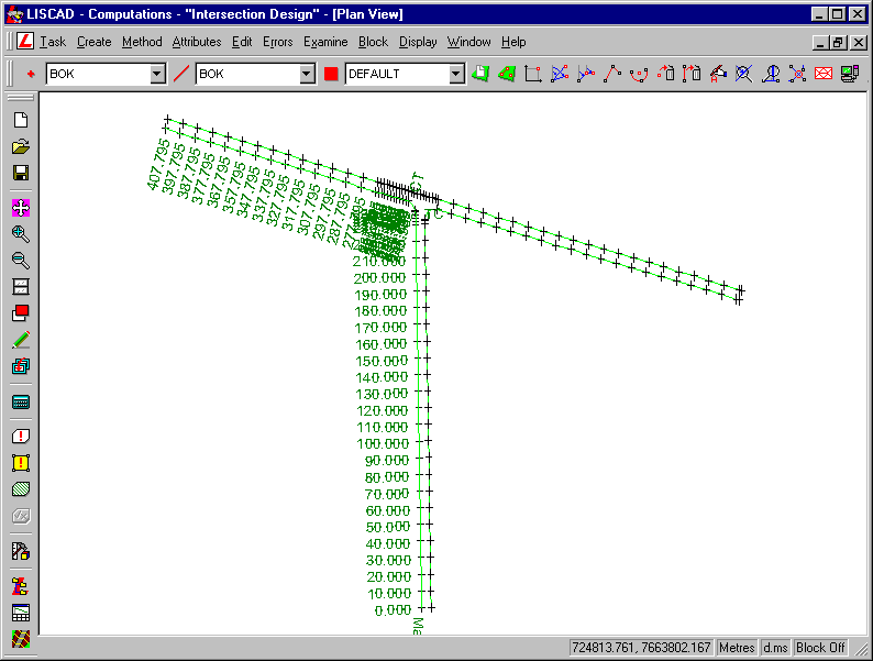
Now create an alignment along the east side of Main Street, round the arc and the south side of Smith Street. Open the Alignment Attributes dialog and enter the name "Main Street East", also change the Text Position of the Chainages to Middle Right.
- Create Long Sections Along the Back of Kerb Alignments
The next thing we need to do is create long sections along each of these two new alignments. These will be design long sections, so we are using the objects along the alignments (i.e. points), rather than the terrain model.
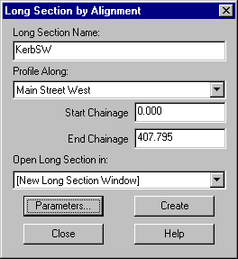
Select Tasks/Profiles and Design/Profile/Long Section/By Alignment, call the new long section "KerbSW", base it along alignment "Main Street West" and select to open it in a new long section window.
In the Parameters dialog, ensure the following is selected.
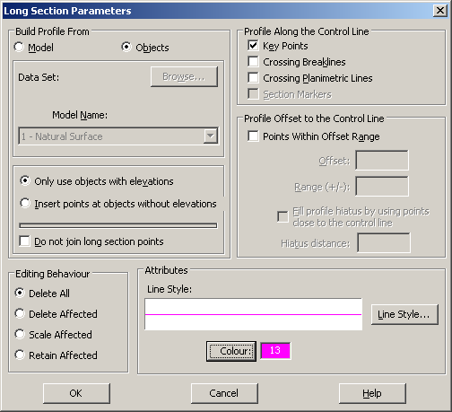
Click OK , then click Create.
This will open up Long Section View:3 and display the long section. Use Display/Features to turn on the horizontal and Vertical geometry, noting where the arc is.
Repeat the process, to create the "KerbSE" long section, based upon the "Main Street East" alignment. Open this up in a new long section window too.
- Create a Kerb Profile Around the Intersection Arcs
We now need to create a Template Implementation Set along parts of these long sections using the "Kerb" template. We only wish to apply it around the arcs, from TP to TP. This will generate the Kerb profile around the arcs between the two streets.
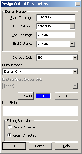
Note that the arc goes from chainage 238.277 to chainage 245.962 on "Main Street West" and from chainage 232.906 to chainage 244.071 on "Main Street East".
We need to create section markers around the arc, in order to add cross sections to these markers.
In Display/Features ensure that Always Display Section Markers is checked in the Alignment tab.
In Plan View, select Create/Section Markers from the Profile and Design task menu and fill in the following...
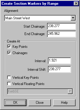
Click OK.
The interval is 1.921 since we want four equally spaced section markers around the arc.
Do this again for the "Main Street East" alignment, using the following values...
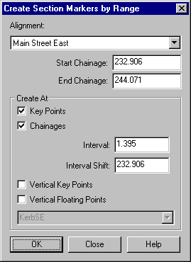
Because this arc is longer than the other, we will increase the amount of section markers to 8 around the arc, hence the interval of 1.395.
Open the Section Manager. Select the "KerbSW" long section, and create a Template Implementation Set for it, using File/Create Template Implementation Set.
Call the Cross Section Set name "KerbSW XS" and set the following...
Control Parameters:
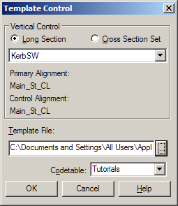
The template file being used is called "IntersectionDesign.tle" and the code table should be set to "Tutorials".
Attach Templates:
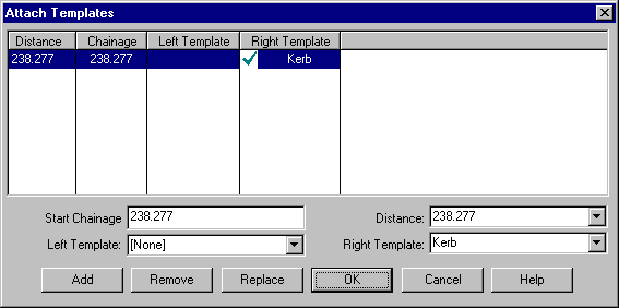
The template "Kerb" has been attached to the Right side of the alignment for the SW alignment.
Output Parameters:
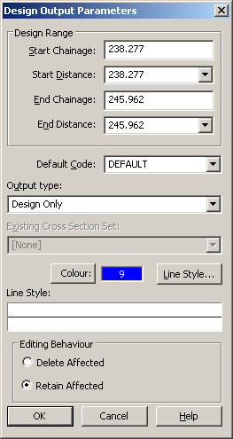
Select a suitable colour and line style and check the output type is "Design Only".
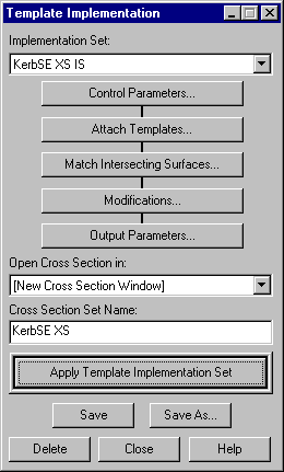
In the main template implementation dialog:
Select Open Cross Section in to a new cross section window.
Select Apply Template Implementation Set to create the "KerbSW XS" cross section set.
Save and close the dialog.
In the Cross Section window, use Display / Features to click on the Template location and Code for Point Attributes.
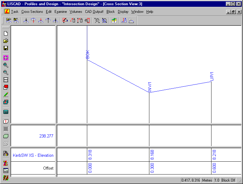
Now create a "KerbSE XS" cross section set along the "KerbSE" long section, by creating a Template Implementation Set as before. Note though that there is one difference, the Kerb profile should be applied to the Left side of the alignment this time.
Attach Templates:
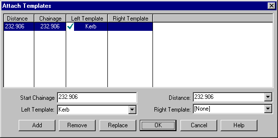
The template "Kerb" has been attached to the Left side of the alignment for the SE alignment.
- Transfer the Kerb Cross Sections into Plan
In Plan View, select Task/Profiles and Design/Profile/Transfer Cross Sections to Plan.
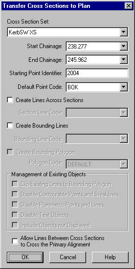
For the "Kerb SW XS" set, set the Start ID to SW, and for the "KerbSW XS" set, set the Start ID to SE. For example, here is the Dialog for the SW set.
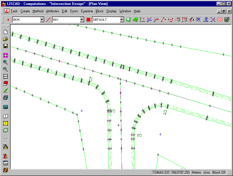
After transferring the cross sections to plan, inspect the kerb design in plan view, turning on all groups. You may find you need to tidy up some line work around the kerb, depending upon what points you deleted from the intersection earlier in the tutorial.
- Disable the Original Surface Data Within the Design Area
Lastly, we should create a terrain model of the design points to ensure that everything is OK. Before we do this however we need to disable the points contained within the design area that were used to form the original natural surface model. We will do this by creating a Polygon Block from the BATTER lines which define the extents of the design works.
Turn all groups off except for the BATTER group.
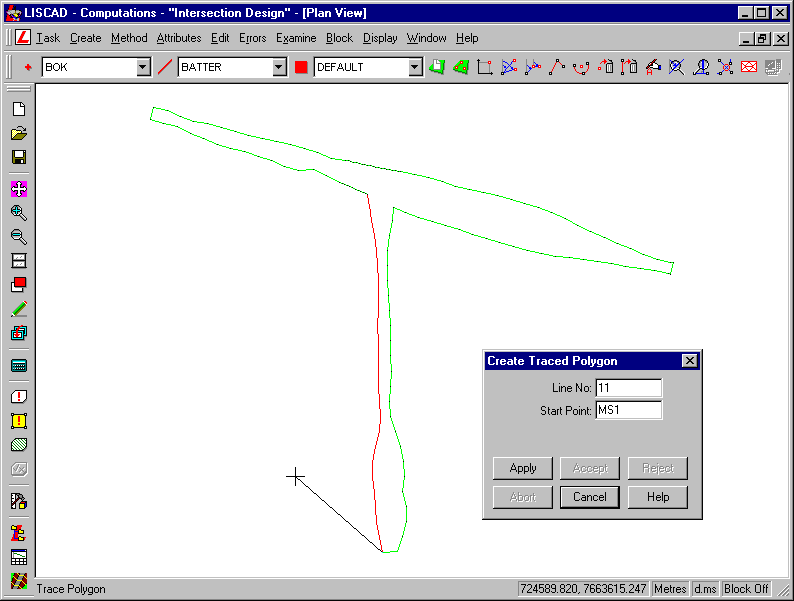
To make a Polygon from these lines you will need to join across the ends of the roads. Set the Line code to BATTER and use Computations / Create Line by Existing Points to join across the 3 open ends to form a closed figure.
Now use Computations / Create Polygon by Trace and click on to one of the lines to form a Polygon.
Now go to Block / Polygon and enter 1.
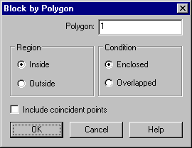
Press OK and a Block will be formed from the BATTER lines. Now turn on the DTM group and turn off the BATTER group.
The DTM group contains the points that the original model was formed from.
Go to Display / Features and check on Display Disabled Objects. This will allow you to see the points that are going to be disabled.
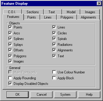
Now go to Computations / Edit / Enable/Disable and make the following settings.
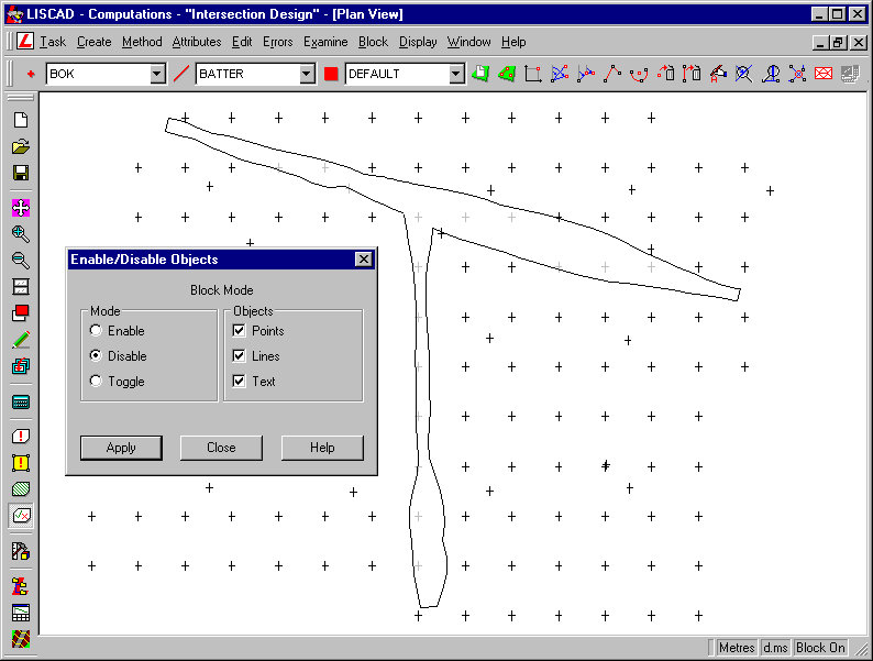
Press Apply and everything on the DTM group inside the Block will be disabled. Disabled objects will not be used in model formation, which means that all the original points inside the design area will not be used, but all original points outside the design area will still be used. Disabling is preferable to deleting as the objects are not removed from the data base and the process can always be reversed at any time.
You can now turn all groups on using Display/Groups.
- Form a Digital Terrain Model of the Design Integrated into
the Existing Surface
Select Tasks/Terrain Modelling/Modelling/Validate. Ensure every box is checked, and validate the model.
You may find that there are a few errors. Some points are recorded as having the same co-ordinate location. This is not a problem as they are points that have computed at the same position. If you wish, these errors can be removed using the Utilities/Maintenance/Filter Points command with a tolerance of 0.001m.
The other errors relate to crossing breaklines. These are caused by the lines that were added across the ends of the road to create the polygon block. These end lines can either be deleted, or the points that define the cross section profile of the road can be inserted into the lines across the end using the Comps/Edit/Insert command.
None of the errors found in the validation should have any noticeable effect on the formation of the model.
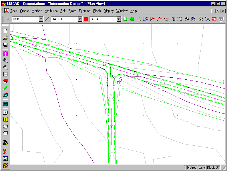
Once everything is in order, perform the modelling via Modelling/Form Model.
Conclusion
You have now completed this tutorial and have been exposed to the steps to be considered in designing a road intersection.