To complete this tutorial you will require the Background
Images module.
Note: This tutorial cannot be completed using LISCAD Lite.
Aim
The aim of this tutorial is to demonstrate how Background Images can be used to 'detail' subject such as building elevations from suitable images. It will look at processing images taken square to the face of the building as well as oblique to the face.
Scenario
A control survey has been conducted using a reflectorless Total Station of the face of the building. This survey has been downloaded and transformed into the plane of the façade. This process has been undertaken in the tutorial "Building Façade Control Survey".
Photographs of the face of the building were also taken using a digital camera. Photos were taken approximately square to the face of the building as well as oblique to the face.
Before you begin
Select this button to install the required data files.
- Create a New File
 Create a new file by selecting File/New…
Enter the File name: as "Elevation" and the Projection type: as Plane and click on the OK button.
- Merge the Control Points into the Empty File
The points in the file "Elevation Control.see" will be used to ‘control’ the background image, and these will be imported into this job using the Merge command.
 Merge the ‘Control’ points in "Elevation Control.see" by selecting
Task/Utilities/Edit/Merge in a File…
 Double click in the "Elevation Control.see" file name and click the Merge button.
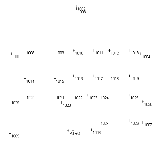
The points that will be used to ‘control’ the background image are displayed.
 For clarity you may wish to use the Display/Features… option
to set Points to display only the Identifier
and Crosses.
 - Import a New Background Image
 Open a background image by selecting Task/Background Images/Registration/Import
and Register Image…
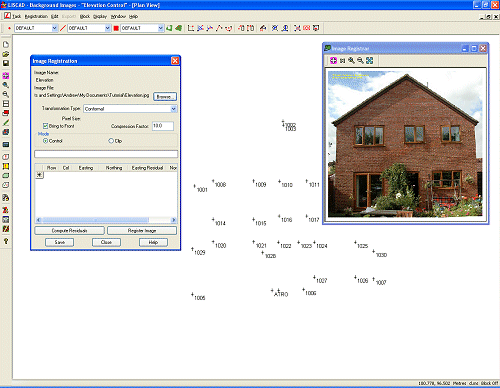
Double click on the file "Elevation.jpg" to select the image to use for this exercise, which will result in the Image Registration dialog and Image Registrar window being displayed.
Four transformations are available:
Conformal - Minimum of 2 control points;
Affine - Minimum of 3 control points;
2nd Order Polynomial - Minimum of 6 control points;
3rd Order Polynomial - Minimum of 11 control points.This exercise takes you through all four options in turn so that you can see the effects of each.
- Register the Background Image Using a Conformal Transformation
Without Redundancy
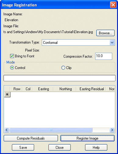
Set the Transformation Type: to Conformal and ensure that the Bring to Front box is checked, Compression Factor: is set to 10.0 and Mode selected as Control.
Click on the
 in the Image Registration dialog.
Note: A compression factor can be entered in the range 1 to 100. A value of 1 will give the largest image file size with the best looking image. A value of 100 will give the smallest image file size but will have a large number of image artifacts causing detail to be lost. A value of 10 gives a good compromise between reasonably compact size and not too many artefacts being introduced. Use the largest compression factor that still retains the image detail you are satisfied with.
 Zoom In to the top right of the Image Registrar window
by activating the icon and clicking on the image.
Zoom In to the top right of the Image Registrar window
by activating the icon and clicking on the image.When you have ‘zoomed’ in sufficiently, switch off the ‘zooming in’ option by either a right mouse click of by clicking on the icon.
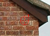
Click the on the junction of the mortar between the bricks at the point shown. This is registered as 1 in the Image Registration dialog.
Click point 1004 of the merged in Control Points.

The first point in the image has been registered.
Click on the
 in the Image Registration dialog.
Move to the lower left corner of the elevation.
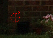
Click the on the junction of the mortar between the bricks at the point shown. This is registered as 2 in the Image Registration dialog.
Click point 1005 of the merged in Control Points.

Two points in the image have now been registered, so there is the minimum number required for a Conformal Transformation.
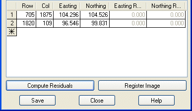
Clicking the Compute Residuals button will display zeros as the two points are the minimum number required for a Conformal Transformation, so there is no redundancy.
Click the Register Image button to fit the image to the two registered points.
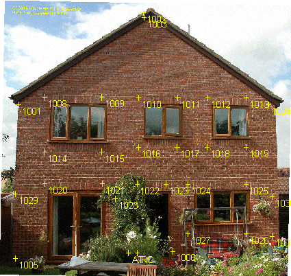
You will notice that the image has been ‘fitted’ to points 1004 and 1005 but we don't really know how well all the other points match their measured positions in the image.
The Conformal Transformation has moved, rotated and scaled the image to fit the two control points exactly, without performing any other action.
- Change the Colour of the Points
You may wish to change the points to yellow for better clarity. To achieve this …
 Use Task/Computations/Attributes/Points… to display the
Point Attributes dialog box.
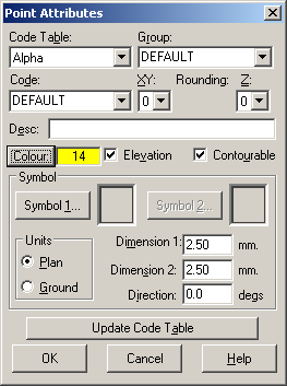
In the Point Attributes dialog change the Colour to Yellow (or whichever colour you prefer).
Note: The attributes in this dialog are the active attributes irrespective of the Code. If you wish to permanently change the Point Attributes for the selected Code you can update the Code Table by clicking the Update Code Table button, but no changes are made to the Code Table by altering attributes in this dialog if this button is not clicked.
Click OK to accept the Point Attributes.
 Select all the points using Block/All.
 Use Task/Computations/Edit/Attributes/Point… to display the
Edit Point dialog.
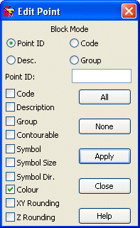
In the Edit Point dialog click None to ensure that all options are cleared so that you do not accidentally change an attribute that you do not intend to. Check the box next to Colour (third from the bottom). Click Apply to make the colour change, and then click Close.
Note: If the colour does not appear to change then you are probably using the colours for Entities rather than the Colour Numbers.
Click Close.
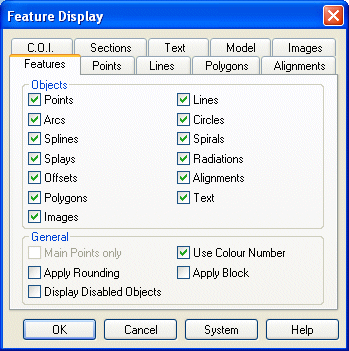
To use the Colour Numbers, select Display/Features… and select the Features tab. In the General panel at the bottom check the box against Use Colour Number.
- Register the Image Using a Conformal Transformation With
Redundancy
 To return to the background image select Task/Background Images/Registration/Check
Image Registration…
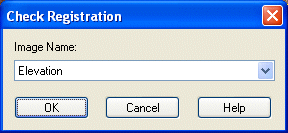
Click OK to accept the Elevation image.
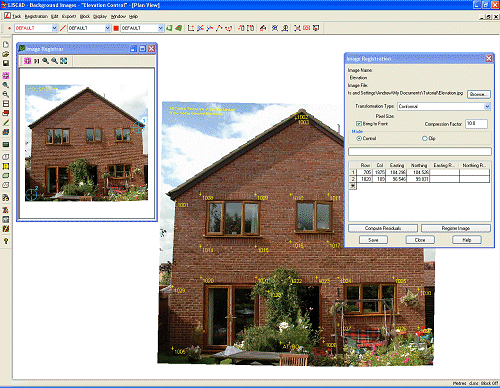
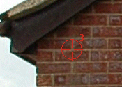
Move to the top left corner of the elevation.
Click on the
 in the Image Registration dialog.
Click the on the junction of the mortar between the bricks at the point shown. This is registered as 3 in the Image Registration dialog.
Click point 1001 of the merged in Control Points.

Three points in the image have now been registered, so there is now more than the minimum number required for a Conformal Transformation.
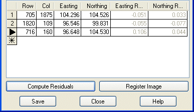
Clicking the Compute Residuals button will display Residual values for the Eastings and Northings for each of the three points.
Click the Register Image button to fit the image to the three registered points.
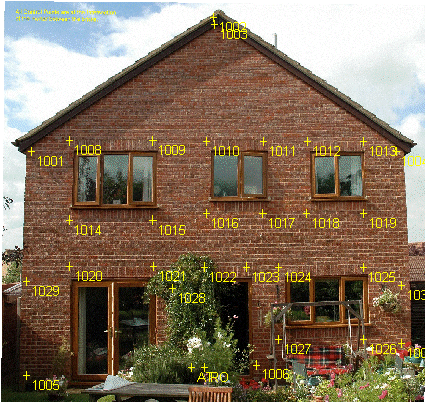
You will notice that the image is now a ‘best fit’ to points 1001, 1004 and 1005 which gives us an idea of the magnitude of the error at the other measured points.
The Conformal Transformation has moved, rotated and scaled the image to fit the 3 control points, without performing any other action.
- Register the Background Image Using an Affine Transformation
Without Redundancy
 Return to the background image by selecting Task/Background Images/Registration/Check
Image Registration…
Return to the background image by selecting Task/Background Images/Registration/Check
Image Registration…Click OK to accept the Elevation image.
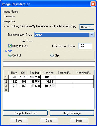
Change the Transformation Type: to Affine.

Clicking the Compute Residuals button will display zeros as the three points are the minimum number required for an Affine Transformation, so there is no redundancy.
Click the Register Image button to fit the image to the three registered points.
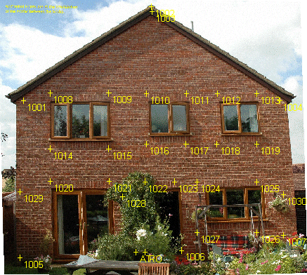
You will notice that the image has now been 'stretched' to achieve an exact fit to points 1001, 1004 and 1005.
The Affine Transformation has moved, rotated and uniformly scaled the image independently in the X and Y axes to exactly fit the control points. Once again we do not know what the error is at the other observed points, but we can probably safely assume that it is better than either of the Conformal transformations performed previously.
However, using the minimum of three points still leaves considerable scope for improvement.
- Register the Background Image Using an Affine Transformation
With Redundancy
 Return to the background image by selecting Task/Background Images/Registration/Check
Image Registration…
Return to the background image by selecting Task/Background Images/Registration/Check
Image Registration…Click OK to accept the Elevation image.
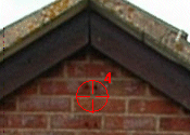
Move to the apex of the elevation.
Click on the
 in the Image Registration dialog.
Click the on the junction of the mortar between the bricks at the point shown. This is registered as 4 in the Image Registration dialog.
Click point 1003 of the merged in Control Points.
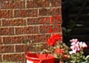
Move to the lower right of the elevation.
Click on the
 in the Image Registration dialog.
Click the on the junction of the mortar between the bricks at the point shown. This is registered as 5 in the Image Registration dialog.
Click point 1007 of the merged in Control Points.
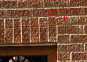
Move to the top right of the single door in the centre of the elevation.
Click on the
 in the Image Registration dialog.
Click the on the junction of the mortar between the bricks at the point shown. This is registered as 6 in the Image Registration dialog.
Click point 1023 of the merged in Control Points.
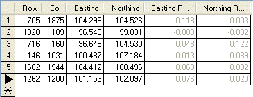
Clicking the Compute Residuals button will display Residual values for the Eastings and Northings for each of the six points. Although all the control points on the face of the building are in a plane, there are distortions in the image, which is why the values for the residuals are quite large.
There are three main sources of distortions in this image:
- The image has not been rectified as the image has been projected on to the plane of the camera through the focal point of the lens;
- The camera was not held exactly at right angles to the plane of the building;
- Lens distortion. As we have not used a calibrated terrestrial photogrammetric camera these distortions can be quite large. Although lens distortion can be determined, it is not uniform across the image. It is usually greater around the edges of the lens.
Click the Register Image button to fit the image to the six registered points.
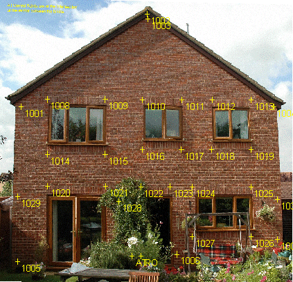
Although the Affine Transformation does scale differently in the X and Y Directions to 'stretch' the image, it is however a uniform but different stretch along each axis, unlike the above mentioned distortions which vary at different positions in the image.
If you zoom in and examine each of the control points it is apparent that the average error from the 'best fit' is about the equivalent of the height of a brick. Certainly not good enough to take measurements from.
The Affine transformation is best suited to orthographic images or maps drawn to scale.
- Register the Background Image Using a 2nd Order Polynomial
Transformation Without Redundancy
 Return to the background image by selecting Task/Background Images/Registration/Check
Image Registration…
Return to the background image by selecting Task/Background Images/Registration/Check
Image Registration…Click OK to accept the Elevation image.
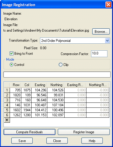
Change the Transformation Type: to 2nd Order Polynomial.
Clicking the Compute Residuals button will display zeros as six points are the minimum number required for a 2nd Order Polynomial Transformation.
Click the Register Image button to fit the image to the six registered points.
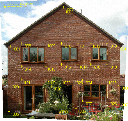
You will notice once again that because we do not have any redundancy the six control points match exactly, but we do not know what the error is at our other measured points.
To get an idea of the errors we should add some more control points to give the solution some redundancy to see what the 'best fit' looks like.
- Register the Background Image Using a 2nd Order Polynomial
Transformation With Redundancy
 Return to the background image by selecting Task/Background Images/Registration/Check
Image Registration…
Return to the background image by selecting Task/Background Images/Registration/Check
Image Registration…Click OK to accept the Elevation image.
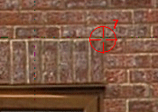
Move to the top right corner of the top left window.
Click on the
 in the Image Registration dialog.
Click the on the junction of the mortar between the bricks at the point shown. This is registered as 7 in the Image Registration dialog.
Click point 1009 of the merged in Control Points.
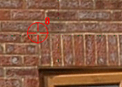
Move to the top left corner of the top right window.
Click on the
 in the Image Registration dialog.
Click the on the junction of the mortar between the bricks at the point shown. This is registered as 8 in the Image Registration dialog.
Click point 1012 of the merged in Control Points.
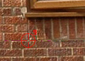
Move to the bottom left corner of the top right window.
Click on the
 in the Image Registration dialog.
Click the on the junction of the mortar between the bricks at the point shown. This is registered as 9 in the Image Registration dialog.
Click point 1018 of the merged in Control Points.
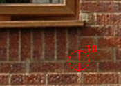
Move to the bottom right corner of the top left window.
Click on the
 in the Image Registration dialog.
Click the on the junction of the mortar between the bricks at the point shown. This is registered as 10 in the Image Registration dialog.
Click point 1015 of the merged in Control Points.
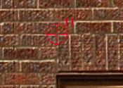
Move to the top left corner of the double doors at the bottom left of the elevation.
Click on the
 in the Image Registration dialog.
Click the on the junction of the mortar between the bricks at the point shown. This is registered as 11 in the Image Registration dialog.
Click point 1020 of the merged in Control Points.
Clicking the Compute Residuals button will display Residual values for the Eastings and Northings for each of the eleven points.
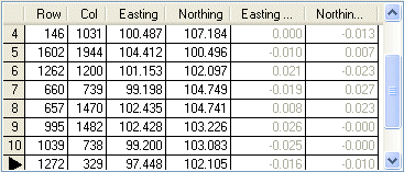
You should notice a marked improvement in the values for the residuals.
Click the Register Image button to fit the image to the eleven registered points.
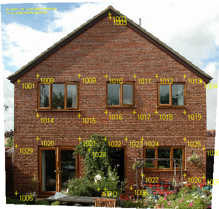
If you zoom in and examine the control points you will now see that the average error is around 2cm.
Can we still improve on these results?
- Register the Background Image Using a 3rd Order Polynomial
Transformation Without Redundancy
 Return to the background image by selecting Task/Background Images/Registration/Check
Image Registration…
Return to the background image by selecting Task/Background Images/Registration/Check
Image Registration…Click OK to accept the Elevation image.
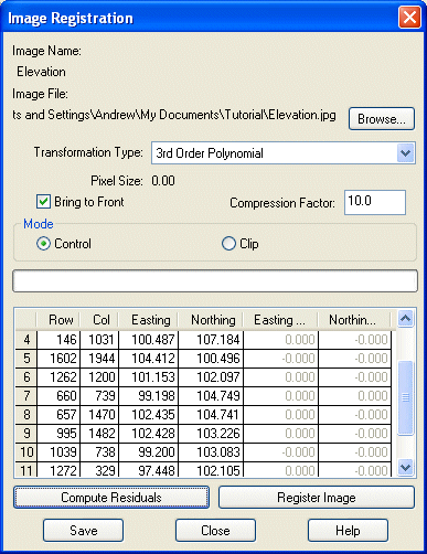
Change the Transformation Type: to 3rd Order Polynomial.
Clicking the Compute Residuals button will display zeros as eleven points are the minimum number required for a 3rd Order Polynomial Transformation.
Click the Register Image button to fit the image to the six registered points.
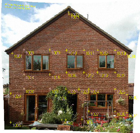
Notice that the distortion of the image has changed, particularly towards the edges which has received greater correction. This is to be expected as the distortions in the image are greater around the edges. You may find that the distortion in your image is slightly different to the example here, but that will be due to your interpretation of which pixels to select for the control points in the image. Essentially the sides of the building should appear to rise vertically without any bends or tapering and all the window and door frames should appear square. If this is not the case check the control points around the area of greatest variation.
You will notice once again that because we do not have any redundancy the eleven control points match exactly, but we do not know what the error is at our other measured points.
To get an idea of the errors we should add some more control points to give the solution some redundancy to see what the 'best fit' looks like.
- Register the Background Image Using a 3rd Order Polynomial
Transformation With Redundancy
 Return to the background image by selecting Task/Background Images/Registration/Check
Image Registration…
Return to the background image by selecting Task/Background Images/Registration/Check
Image Registration…Click OK to accept the Elevation image.
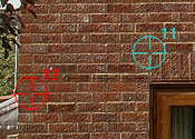
Move to the left of the top of the double doors at the bottom left of the elevation.
Click on the
 in the Image Registration dialog.
Click the on the junction of the mortar between the bricks at the point shown. This is registered as 12 in the Image Registration dialog.
Click point 1029 of the merged in Control Points.
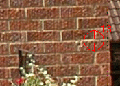
Move to the right of the top right corner of the bottom right window.
Click on the
 in the Image Registration dialog.
Click the on the junction of the mortar between the bricks at the point shown. This is registered as 13 in the Image Registration dialog.
Click point 1030 of the merged in Control Points.
Clicking the Compute Residuals button will display Residual values for the Eastings and Northings for each of the thirteen points.
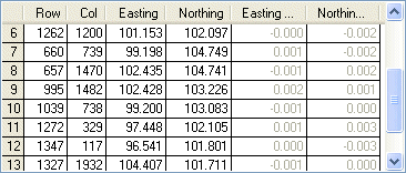
You should notice a significant improvement in the values for the residuals using the 3rd Order Polynomial solution.
Click the Register Image button to fit the image to the thirteen registered points.

If you zoom in and examine the control points you will now see that the average error is generally less than the width of the mortar between the bricks.
Although in general the results look good, there are some points where the error is significantly larger. The error is greatest around points 1006, 1027 and 1026. This is because the polynomial transformations work on the basis of minimising the errors around the control points and pushing the errors as far away from the control and towards the edges as possible. As we have registered less control points along the bottom edge of the image this is where the errors have been pushed.
Polynomial transformations work the best if there is good control around the edge of the image and the distribution of control across the image is at regular spacing.
Try registering the control point 1027 with the bottom left corner of the lower window to see if this improves the solution.
This image was taken so that the plane of the image was close to the plane of the building façade. Unfortunately it is not always possible to position the camera at the ideal location. Let us now have a look at what happens when we take an oblique photo that has significant perspective distortion introduced.
- Register an Oblique Background Image Using a 3rd Order
Polynomial Transformation With Redundancy
Repeat this exercise, but this time Import and Register the new image "Elevation Oblique.jpg".
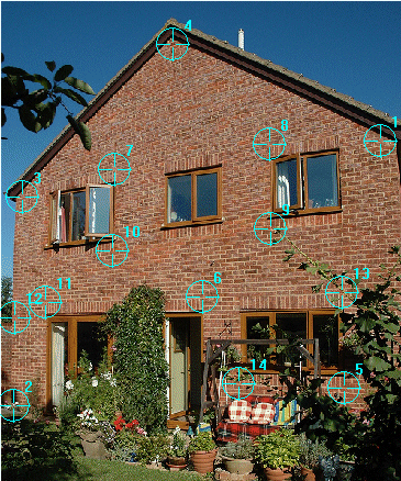
Use the same control points as before except for registration points 5 and 13 which have been replaced by new control points as they are obscured in the oblique photo.
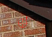
Registration Point 1 - Control Point 1004 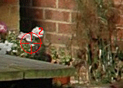
Registration Point 2 - Control Point 1005 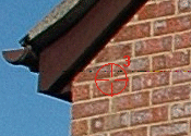
Registration Point 3 - Control Point 1001 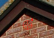
Registration Point 4 - Control Point 1003 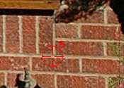
Registration Point 5 - Control Point 1026. Move to the lower right corner of the lower right window. Click the on the junction of the mortar between the bricks at the point shown.
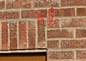
Registration Point 6 - Control Point 1023 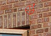
Registration Point 7 - Control Point 1009 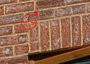
Registration Point 8 - Control Point 1012 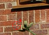
Registration Point 9 - Control Point 1018 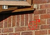
Registration Point 10 - Control Point 1015 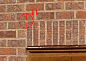
Registration Point 11 - Control Point 1020 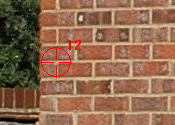
Registration Point 12 - Control Point 1029 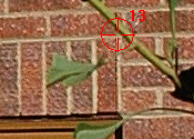
Registration Point 13 - Control Point 1025. Move to the top right corner of the lower right window. Click the on the junction of the mortar between the bricks at the point shown.
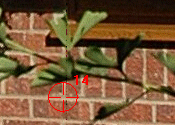
Registration Point 14 - Control Point 1027. Move to the lower left corner of the lower right window. Click the on the junction of the mortar between the bricks at the point shown.
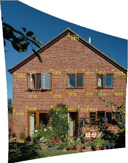
As you can see the distortion of this image is substantial, but the house walls are vertical and the windows and doors are all square.
If you zoom in on the control points you should observe that the errors are minimal.
The reason this Tutorial works well for both images is because all the control points are in the same plane. If you have a building façade with many protrusions and indentations it is very important that you select control points that are in the same plane. Measurements taken to the protrusions and indentations will be in error depending upon how far the point is in front of or behind the control plane.
If you have a building that is not on a single plane you should take separate photos of the individual façade planes. These photos should then be registered independently in Background Images. You can work with the images independently within LISCAD, by turning them on and off as required, to map the features in the different planes.
As noted earlier, one of the errors inherent in the photo that has been removed by the transformation is lens distortion. Cheaper cameras and wider angle lenses will more than likely have greater lens distortion than the higher end cameras. In either case though lens distortion will still be present. If lens distortion can be removed from the image prior to registration then the chances are that less control points will be required and a 2nd order polynomial transformation may give you the accuracy you require.
There are third party products available which allow you to remove lens distortion from your photos. These work by providing distortion profiles for your particular lens which can then be applied to the image. You may wish to check out PTLens, a freeware application that corrects lens distortion for a large number of digital SLR cameras.
Conclusion
You have now completed the Background Images Tutorial and should have a good understanding of the following:
- How to import and register an image;
- How the different transformations apply to façade images;
- That polynomial transformations should be used for façade images;
- That it is important to have redundant control points in order to get a determination of the errors involved;
- That errors are in the original image due to perspective and lens distortion;
- That all the control points should lie on the same plane;
- That there will be positional errors in points that are in front of or behind the control plane.