To complete this tutorial you will require the Input/Output
and Computations modules.
Note: This tutorial cannot be completed using LISCAD Lite.
Aim
By default the Plan View in LISCAD SEE is set so that the X direction represents the Easting component and the Y direction represents the Northing component. If you have undertaken a survey of a building façade and import it into LISCAD by default it will be plotted in the Plan View as though you are looking down upon the building. With these types of surveys it is more appropriate to view the survey as though you are facing the front of the building.
The aim of this tutorial is to process a field survey that has been conducted of the face of a building and transform the axes it so that it is displayed facing you.
Scenario
A conventional survey of a building façade has been undertaken, using a Leica TPS-1100 reflectorless total station, which requires importing into LISCAD.
Before you begin
Select this button to install the required data files.
- Create a New File
 Create a new file by selecting File/New...
Enter the File name: as "Elevation Control" and the Projection type: as Plane and click on the OK button.
- Reduce the Field Survey
 Create a Field File from the raw GSI data file by selecting Task/Field
Transfer/Resolve/Create Field File...
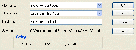
Set the Files of type: to Leica Gsi Files (*.gsi).
Select the input File name: "Elevation Control.gsi", and the output Field File: should automatically set itself to "Elevation Control.fld".
This will result in the file "Elevation Control.gsi" being read and converted into the standard LISCAD format field file "Elevation Control.fld".
Click OK to accept the default file names.
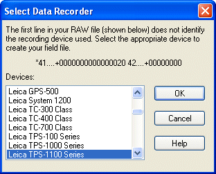
Select Leica TPS-1100 Series in the Select Data Recorder panel, and click OK.
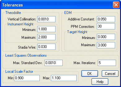
As a reflectorless total station has been used we should set the target height tolerances to indicate that there is no height to the target.
Select Task/Field Transfer/Settings/Tolerances and enter a EDM-Target Height - Minimum: of 0.000.
 Reduce the Field File by selecting Task/Field Transfer/Resolve/Reduce
Field File...
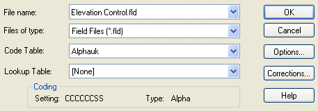
Click OK to accept the default settings displayed.
The LISCAD Report: Field Reduction Error Report will be displayed with a Warning because we have not used any Codes in the measured data.
Warning - Line 10, Code "00000" not in code table - DEFAULT settings used.
1 Warnings detected
Ignore the Warning and close the panel.
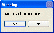
Click the Yes button to continue.
The LISCAD Report: Field Reduction Error Report will again be displayed, but this time with two Warnings because we have not used any Codes in the measured data, and the Occupied Station co-ordinates have been recorded twice in the GSI data file.
Warning - Line   10, Code "00000" not in code table - DEFAULT settings used.
1 Warnings detected

Duplicate - Line   14, Pt: AT dX:  0.000 dY:  0.000 dZ:  0.000
1 Reduction Messages
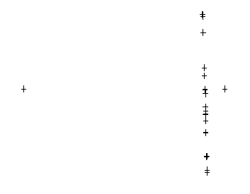
The measured points are displayed to the screen, but are in plan on the arbitrary datum on which they were observed. These points need to be ‘reorganised’ to be in the plane of the façade and useful for controlling the image we wish to rectify with the "Façade Background Images" Tutorial.
For the points to be useful, we must first use Rotate to align the points on the façade along the X axis, and then use Exchange Axes to swap the Y and Z co-ordinates.
- Rotate the Building Façade to Align With the X Axis
 To rotate all the points together select all the points using Block/All.
 Open the rotate dialogue by selecting Task/Computations/Edit/Rotate...
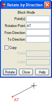
The Rotate by Direction dialogue is in Block Mode so the cursor is at the Rotation Point: edit field. Select the point AT.
Note: The right mouse button is used to snap to the point and the left mouse button to accept the point. With an isolated point, such as AT, the point can be accepted immediately with the left mouse button without having to snap first.
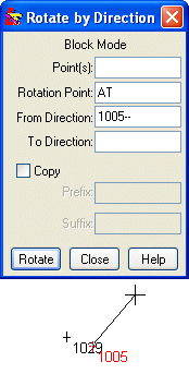
The From Direction: is defined by two points, one at each end of the façade. Select the start point 1005.
Note: The location of point 1005 is congested so select point 1005 with the right mouse then accept the point with the left mouse button.
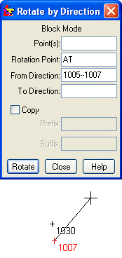
Select the end point 1007. After selecting the points 1005--1007 it will be replaced by the direction between the two points which is 178° 21' 05". If you wish to see how this direction was derived just hold the cursor over the field and it will display the two point identifiers that make up the reference direction.
Note: The location of point 1007 is congested so select point 1007 with the right mouse then accept the point with the left mouse button.
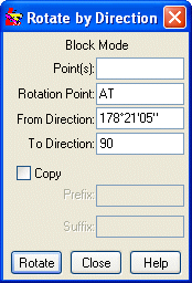
The To Direction: is to be along the X axis, which is at 90° and this value can be entered directly. Enter 90 in the To Direction: field.
Click the Rotate button.
 Use Display/Fit to display the rotated points.
- Exchange the Axes
The measured points are now displayed to the screen with the points on the façade along a ‘line’ in the X axis in ‘plan’ view, but are required in the plane of the façade.
 To exchange the axes of all the points together select all the points using
Block/All.
 Open the exchange axes dialogue by selecting Task/Computations/Edit/Exchange
Axes...
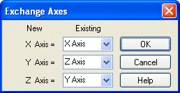
Leave the X Axis = X Axis.
Set the Y Axis = Z Axis.
Set the Z Axis = Y Axis.
Click OK.
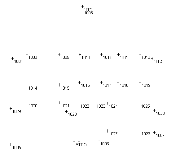
The measured points are now in the plane of the façade and ready for use as control for the image to be used in the "Façade Background Images" Tutorial.
Conclusion
You have now completed the Building Façade Control Survey Tutorial and should have a good understanding of the following:
- Reducing a raw field survey into LISCAD SEE;
- Rotating an entire job;
- Exchanging the axes to view the file in the desired plane.