To complete this tutorial you will require the Background Images module.
Note: This tutorial cannot be completed using LISCAD Lite.
Aim
The aim of this tutorial is to demonstrate how to import and register a bitmap image within LISCAD. It will also show:
- How to clip redundant information from around the image;
- How to control the display of an image once it has been successfully imported.
Scenario
Two existing images have been scanned that are required to be used as a background reference to the works being undertaken. These images are framed with information that is not required to be displayed within LISCAD. The images also overlap each other so it is necessary to control how the images display with respect to each other.
Before you begin
Select this button to install the required data files.
- Open the Control Data File
Open the tutorial file "Background Images.see".
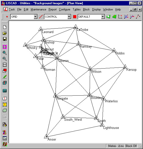
This file shows a triangulation survey of Wilsons Promontory National Park in Victoria, Australia. The file has been created on the UTM Australian Map Grid Zone 55.
Please refer to the tutorial "Creating a New SEE Project on a Projection" if you are not already familiar with this process.
- Import Image
To put this survey into perspective some digitized maps of the region are going to be imported into the file and registered with the projection.
Select Task/Background Images to activate the Background Images module.
Select Registration/Import and Register Image from the main menu. This will display the Open Image dialog. Navigate to the Tutorial Data folder and select the image "Wilsons Prom 100000.tif".
Note: Selecting the file will automatically give it an Image Name the same as the file name. This is the name it will be referred to within LISCAD. The image name does not have to be the same as the file name and can be edited if required.
Press Open to load the image into the Image Registrar Window and open the Image Registration dialog box.
- Establish Registration Control Points
In the Image Registration dialog box set the Transformation Type to "Affine" from the drop down list.
Note: An Affine transformation is usually the best to use when registering a map image. For information on which transformation type to use under what circumstances please refer to the Background Image Concepts in the Help.
We will now create 5 control points with which to register the image.
Use the Fit toolbar button on the Image Registrar window to see the entire map. Now using the 1:1 button, click on the top left hand corner of the image. Use the right hand mouse button to break out of the 1 : 1 command.
2 of the control points will be taken from the grid on the map image, the other 3 control points will be taken from the survey control points in the LISCAD data base.
Ensure that the Mode radio button is set to Control
Click on the * in the coordinate registration table to establish a new registration point.
Move the cursor to the grid intersection shown in the image below (Top Left). To get a closer look use the Zoom In button. Place the cursor over the top of the intersection of the grid lines and press the Accept button on the mouse. If you are not happy with the position, move the pointer to where you want it and press Accept again. Tab to the Easting Field and enter 437000. Tab to the Northing field and enter 5682000. Press Tab again, or click on the *, to establish the next registration point. Place the 2 registration points at the locations shown in the diagrams below and enter the following map coordinates.
Easting Northing 1 437000 5682000 2 456000 5682000 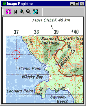
Control Point 1 - Top Left
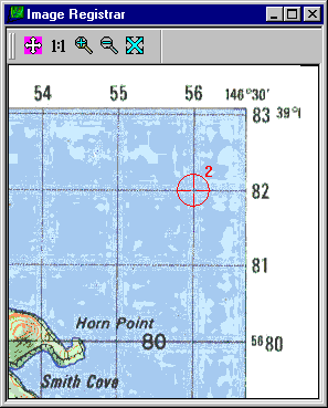
Control Point 2 - Top Right
The next 3 control points are placed on the image in the same way, but instead of typing in the East and North values we will select to the control points in the Plan View window.
First locate Mt Wilson near the centre of the image and place control point 3. Now Snap/Accept to the point named "WILSON" in the plan window. This will transfer the co-ordinates from the data base into the coordinate registration table. There are 3 control points to enter in this manner:
No. Image Point Control Point Location 3 Mt Wilson Wilson Central 4 South Peak South Bottom Right 5 Mt Norgate Norgate Centre Left 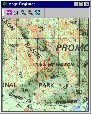
Control Point 3 - Mt Wilson
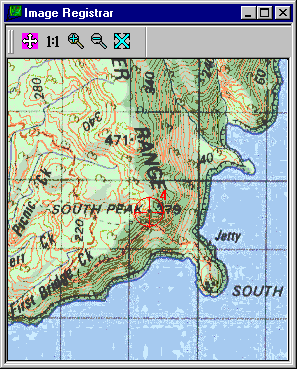
Control Point 4 - South Peak
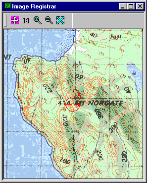
Control Point 5 - Mt Norgate
- Check Residuals
Before registering the image we will check the residuals of our registration. Press the Compute Residuals button to view the errors. If you have established your control points correctly your residuals should be similar those shown below. Your residuals may not be exactly the same as those shown below as it will depend upon which pixels in the image you have decided represents the centre of the control points.
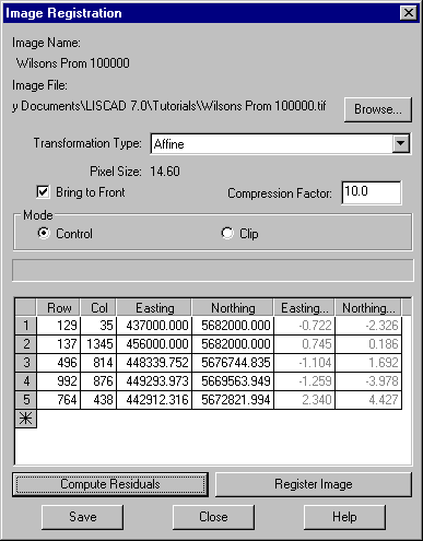
When you compute the residuals the pixel size is also computed. At this scale of 1:100000 each pixel represents a 14.6m square on the ground. Hence if your residuals are well inside this value you should have a good registration. If they are considerably larger, check that you are using the correct transformation type, in this case Affine. If the residuals are still unacceptably large check the map coordinates entered, as well as the selected position for the control point. Start by checking the control point with the largest residuals. After making any adjustments press the Compute Residuals button again to check if the residuals are now acceptable.
- Register the Image
Once you are happy with the residuals, set the Compression Factor to 10.0 and press the Register Image button. A gas gauge tracks the image registration process as the image is imported into the SEE file and transformed to match the map projection.
Note 1: A compression factor can be entered in the range 1 to 100. A value of 1 will give the largest image file size but the best looking image. A value of 100 will give the smallest image file size but will have a large number of image artifacts causing detail to be lost. A value of 10 gives a good compromise between reasonably compact size and not too many artifacts being introduced. Use the largest compression factor that still retains the image detail you are satisfied with.
Note 2: The original image is displayed based upon a conformal grid of Latitudes and Longitudes. Our project is displayed based upon a conformal grid of Eastings and Northings. The transformation process will square up the image so that the image is corrected to match the Easting/Northing display.
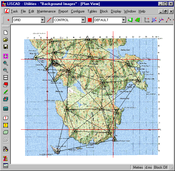
When this process is complete the image registration dialog box and window will close down and the transformed image will be displayed in the plan window.
To verify that the transformation was successful, grid lines have been entered into this job. To view these grid lines select Display/Groups and press All to turn on all groups. If the transformation is correct the vector grid lines should lie over the top of the image grid lines. Use the Zoom, Window and Pan functions to confirm that the image matches the grid and survey.
- Clip the Image
Our next step is to remove the labelling from the North and East edges of the map to "clean up" the image. This is also done through the Image Registration process. Open the Image Registration window again by selecting Registration/Check Image Registration from the main menu. This will bring up a dialog box asking you to select the image for checking. "Wilsons Prom 100000" should already be selected so press OK.
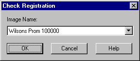
Press the Mode / Clip radio button to set the Image Registration dialog box in Clip Mode. This will disable the Coordinate Control table so you cannot edit the control points.
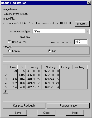
Zoom in on the image so that you can see the top left hand corner. You should see a line around the outside edge of the image. If you are having difficulty identifying the clip line from the image, toggle between Clip and Control mode to turn the clip line on and off. This represents the clip rectangle and by default is set to the full extents of the image. Place the cursor over the top left hand corner and the cursor will change to a hand pointer. Hold the cursor down and drag the corner of the clip rectangle to just inside the edge of the map.
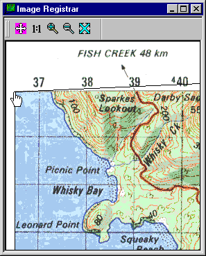
Drag the clip rectangle corner from the top left corner to just inside the map.
Repeat this step for the top right and bottom right corners. There is no need to do the bottom left corner as we only need to clip the top and right side. When the clip rectangle has been placed to your satisfaction press the Register Image button to reprocess the image.
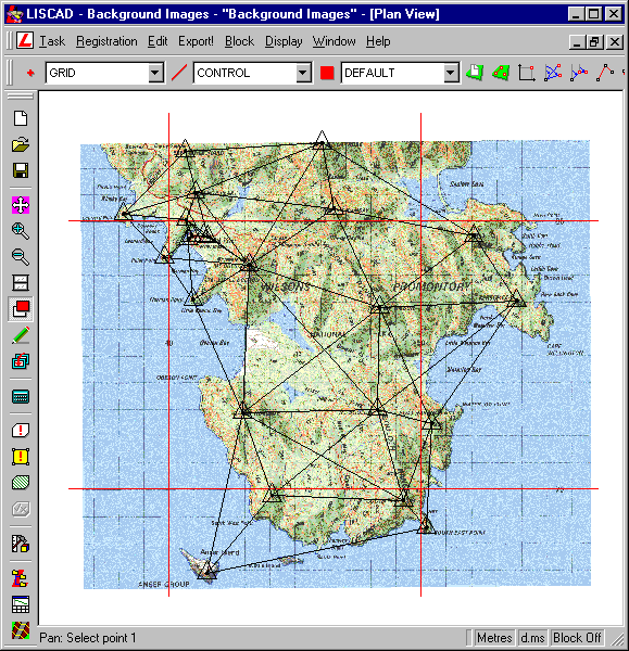
- Import and Register the Second Image
Around the township of Tidal River (North West corner) there has been some more detailed survey work undertaken and the map scale of 1:100000 is too small. To assist with this area a map of 1:25000 has been scanned which we will now import.
Repeat steps 2 through to 5 but this time load image file "Wilsons Prom 25000.tif". Set the control points in the image as shown below, using the map coordinates listed in the table.
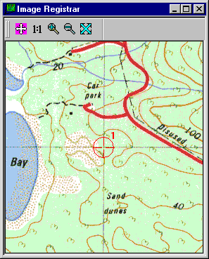
Top Left
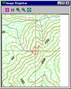
Top Right
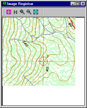
Bottom Right
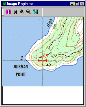
Bottom Centre
Easting Northing 1 439000 5681000 2 444000 5681000 3 444000 5677000 4 441000 5677000 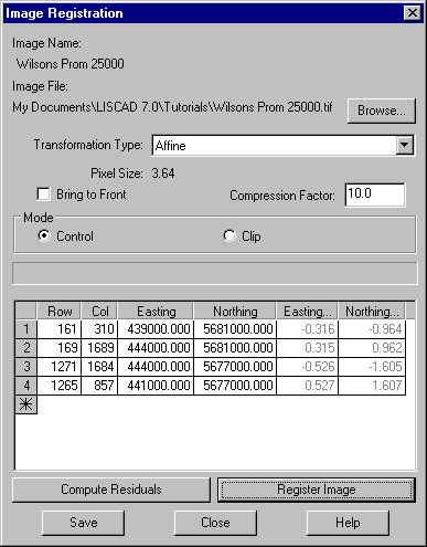
Once again set the image Transformation Type to "Affine" and press the Compute Residuals button. In this image each pixel is approximately 3.6m square on the ground so your residuals should be below this value provided the map is true to scale.
Before registering the image set your required Compression Factor and turn OFF the Bring to Front check box.
Once you are happy with the residuals, press the Register Image button to import and transform the image to the job.
- Controlling the Image Display Order
After the registration process is complete you will find that you cannot see the new imported image. This is because it lies behind the image that was previously imported due to the fact that we turned off the Bring to Front check box. Images are displayed in order from the bottom to the top of the list.
However, the display order can be changed at any time by selecting Display/Features and selecting the Images Tab.
Simply drag and drop the "Wilsons Prom 25000" image to the top of the list, alternatively click on it and press the Up button.
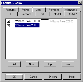
Note that the check box next to each image allows you to turn the display of the images on and off as required.
Press OK to display the 1:25000 image over the top of the 1:100000 image.
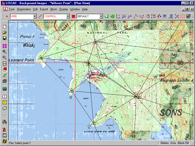
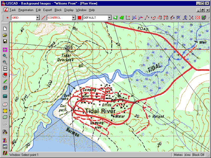
Window in on the image to check that it is correctly registered with the other image, the grid lines and the survey control.
Conclusion
You have now completed the Background Images Tutorial and should have a good understanding of the following:
- How to import and register an image;
- How to check that the transformation residuals are acceptable;
- How to clip redundant information from around the edge of an image;
- How to control the display order of multiple images in the file.