To complete this tutorial you will require the Computations module.
Note: This tutorial cannot be completed using LISCAD Lite.
Aim
The aim of this tutorial is to create a new SEE project based on a projection. You will also be exposed to:
- Controlling what features are displayed.
- Selecting code tables and codes to control attributes of new objects being created.
- Creating points and lines.
- Controlling the precision of display for bearings.
- Controlling which type of bearing and distance is displayed.
Typical Scenario
A typical scenario for using a projection project would be:
"The survey is in the region covered by the Australian Map Grid (AMG) Zone 55. There are control points with known AMG Zone 55 co-ordinates that are the datum for the survey."
Before you begin
Select this button to install the required codetable.
Now proceed with the steps below.
- Install the Required Projection
First we will check if the Australian Map Grid (AMG) Zone 55 co-ordinate system is installed on your system.
Run SEE and select Configure / Projections / Install/Remove to display the Install/Remove Projections dialog box.
Set the Projection Type to "Transverse Mercator".
Look in the Installed Projections list to see if the "Australian Map Grid Zone 55" projection is installed.
If it is not installed, locate it in the Available Projections list, click on it and press the Install button. (While you are here it is probably a good time to identify any projections you use on a regular basis and install them now.)
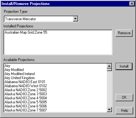
Press OK to accept your changes and close the dialog.
- Open the New File Dialog Box
Select File/New to display the New File dialog.
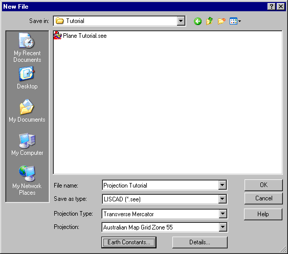
Use the Save In field to navigate to your Data folder.
Click in the File name: field and type "Projection Tutorial".
Use the Projection Type: drop down list to select "Transverse Mercator".
From the Projection: drop down list select "Australian Map Grid Zone 55".
- Set-up the Earth Constants
Select the Earth Constants button and ensure the dialog fields are as shown below.
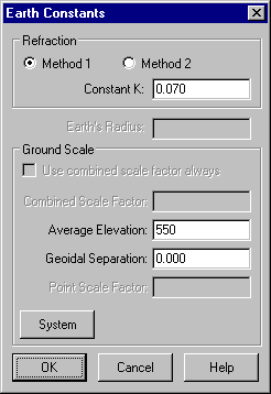
Ensure that the Average Elevation is set to 550. This value is used to calculate sea level correction for points that do not have an elevation.
Ensure that the Geoidal Separation is set to 0, by which we are assuming that the geoid and ellipsoid are coincident in the area of the survey.
As the project is to be on a projection, the corrections between ground and grid distances are applied automatically. (Sea level correction is based on the point elevations; scale is based on the point positions.)
Select OK to return to the New File dialog.
- Enter the Project Details and Create the Project
Click the Details button, enter any details you wish in the available fields, then press OK to return to the New File dialog.
Click OK to create the new project. The new project is now automatically opened.
- Set the Display Attributes for the Points and Lines
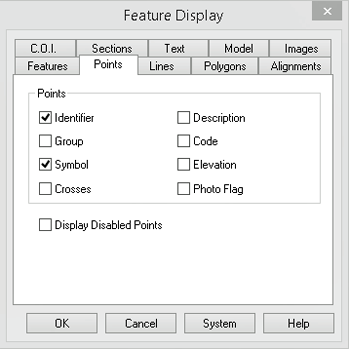
Select the Display/Features command and then the Points tab.
Select Identifier and Symbol. This ensures that you will see the Symbols and Identifiers for any points created.
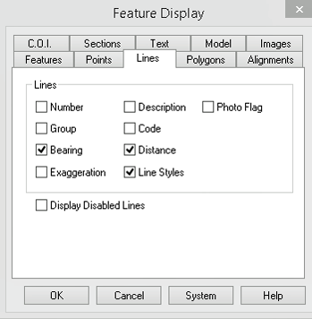
Now select the Lines tab.
Select Bearing, Distance and Line Styles. This ensures that you will see the Bearings, Distances and line styles for any lines created with those attributes.
Tip: You can quickly show the Display Features dialog by right clicking anywhere on the screen and selecting it from the floating menu.
- Select the Code Table and the Required Points and Lines
Codes
The code table that we wish to use is the "Tutorials" code table. Select Tables/Code Table/Open to display the Open Code Table dialog.
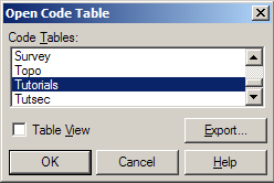
Select "Tutorials" from the available list of code tables, then OK to display the Code Table Editor dialog shown below.
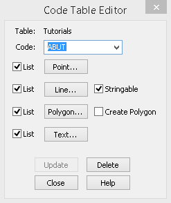
Select Close and the currently active code table will become the "Tutorials" code table.
The code that we wish to use is "PM" which is already available in the selected "Tutorials" code table, and is set with appropriate attributes.
Use the code lists as shown below to select "PM" for the current point code (left in picture) and the current line code (right in picture).

- Create Two Points by Entering Co-ordinates
Select Task/Computations
Then select Create/Point followed by Method/Co-ordinates
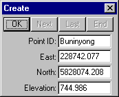
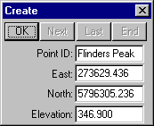
Complete the fields as shown above left and select OK to create point "Buninyong".
Complete the fields as shown above right and select OK to create point "Flinders Peak".
Then close the Create dialog.
- Create a Line Between the Two Points
Select Create/Line and then select Method/Existing Points.

With focus in the Points: field, first snap and accept point "Buninyong", then snap and accept point "Flinders Peak". Then press the End button.
A line between the points is created with bearing and distance attributes as per the line code attributes.
- Set the Bearing Precision
Select Task/Utilities. Then select Configure/Angles to display the Angle Configuration dialog.
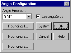
Set the Angle Precision: field as shown to 0.01" and then press OK to close the dialog.
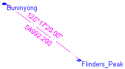
The bearing of the line will now be displayed to the nearest 0.01".
The dimensions shown are Plane Bearing and Grid Distance as these are the current units configuration settings.
- Change the Display to Grid Bearings and Ground Distances
Select Configure/Units and change the units settings to Grid Bearing and Ground distance as shown below. Then press OK to close the dialog.
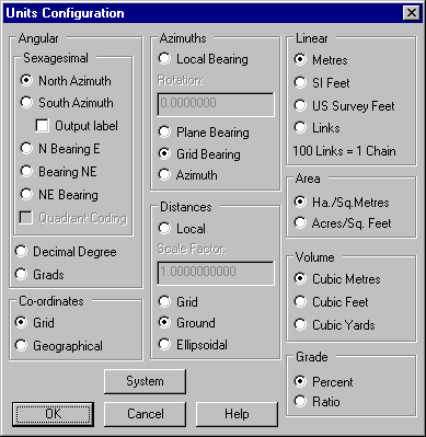
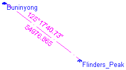
The dimensions now shown are Grid Bearing (from Buninyong to Flinders Peak) Ground Distance.
- Change the Display to Azimuths and Ellipsoidal Distances
Select Configure/Units again and change the units settings to Azimuth and Ellipsoidal distance. Then press OK to close the dialog.
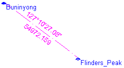
The dimensions now shown are Azimuth and Ellipsoidal Distance.
Conclusion
You have now completed this tutorial and should have a good understanding
of how to create a projection project.
You have also learnt how to:
- Control what features are displayed using Display/Features.
- Select the code table and code you wish to use for the creation of new objects.
- Create points by co-ordinates.
- Create lines by existing points.
- Configure the precision of angle/bearing display.
- Configure units for display of different bearing and distance types.
You should also have an appreciation of the rigorous support of projections provided in SEE, and the extreme flexibility to view or enter dimensions in grid, ellipsoid or ground distance; and in plane, grid or azimuth bearings.