Understand how to create points, lines and polygons on specific layers using a measurement code.
Home / Data / 
Measurements / Process / 
Codes specified for a measurement or Leica free codes preceding the measurement.
A control code table.
When data is imported, or codes are processed from the measurements view, the measurements code determines the layer in which the object is placed. The layer or control code determines the objects display attributes.
| Condition | Behaviour |
|---|---|
| A layer exists with the same name as the code. | The object is placed on the layer and drawn according to the layers display attributes and general attributes. |
| A layer does not exist with the same name as the code but the code ends in numbers. | If Process Codes is selected, the last number is stripped from the code. If a layer exists with the same name as the stripped code the object is placed on the layer and the stripped number is interpreted as the string number and used to join points. This process is repeated until all numbers have been stripped or the stripped code matches a layer name. |
| A layer does not exist with the same name as the code. | A new layer with the same name as the code is created using the display attributes and general attributes of the layer template. If a layer template does not exist the default layers display attributes and general attributes are used. The object is placed on this layer. |
| A point or measurement does not have a code. | The object is placed on the active layer and drawn according to the layers display attributes and general attributes. |
| A layer lookup table maps a code to a layer. | The object is placed on the mapped layer and drawn according to the layers display attributes. |
| A control code definition includes a specified layer. | The object created from processing a control code is placed on the specified layer and drawn according to the layers display attributes. |
Process codes to apply point symbols or create lines, pipe shapes and polygons. You can create linework by processing string numbers, control codes or by joining points with the same measurement code.
String NumbersTo process string numbers do one of the following:
- In the import options, select Process Codes.
- In the measurement processing options, select Process Codes then process the measurments.
Lines are created between measured points with matching codes and string numbers.
Lines are placed on a layer with the same name as the code and drawn according to the layers 'Line' display attributes.
Measurments verticies with matching codes and string numbers are joined by lines in the order they were imported.
When attribute string codes are imported, they are added to the measurement code and displayed with the measurement in the measurement view.
A string code '00' indicates the measurements vertex should not be strung.
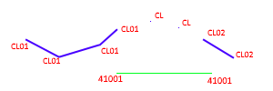
In the following example, if the layer CL and 410 exists in the project, measurements vertices are joined according to their code and string code.
To process control codes, in addition to selecting Process Codes, do one of the following:
- In the import options, select the control code table from the Control Codes list.
- In the measurement processing options, select the control code table from the Control Codes list, then process the measurments.
Control codes are codes used to create symbols, line objects (straights, splines, and arcs) and pipe shapes or remove heights from points measured in the field. Control codes perform a specific action. For example a 'Join Start' control code ends a previous line and starts a new line.
You can specify a control code value for each action in a control codes table.
Use control codes as an alternative to string numbers, onboard line creation, or to perform more complex tasks that are not supported by normal stringing tools.
If the measurments vertices have not already been joined using an alternate method, you can join consecutive points with the same code. To join consecutive points with the same code, in addition to selecting <Process Codes, do one of the following:
- In the import options, select Join Consecutive Point.
- In the measurement processing options, select Join Consecutive Points, then process the measurments.
- If a layer has the intended use set to Lines, all consecutive points with the same code are joined in the order they were imported to form a line.
- If a layer has an intended use of 'Polygons', all consecutive points with the same code are joined in the order they were imported. The last point in the sequence joins back to the first point to form a polygon. A minimum of three consecutive points with the same code is required to form the polygon.
String codes and control codes are still applied when a layers intended use is specified. For example points with a string code of '01' will still form a line when a layers intended use is set to 'Polygon'.
While it is not common to use all code processing methods, the following examples demonstrates different code processing methods and how selecting Process Codes, Process Control Codes, Join Consecutive Points, adding string codes, control codes, and defining the layers Intended Use affects the creation of lines and polygons.
Measurements with the following codes are imported:410, 41001, 41002, BCK, BCK ST, BCK END BCK00
The following layers exist:
410
BCK
The following Coding options are selected on import:
- Process Codes
- Process Control Codes
- Join Consecutive Points
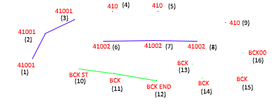
When Point or Generic is selected as all of the layers Intended Use the following will occur:
- Vertices from measurements with the code '41001' are joined in the order they appear in the imported file or database and the line is placed on layer 410.
- Vertices from measurements with the code '41002' are joined in the order they appear in the imported file or database and the line is placed on layer 410.
- Vertices from measurements with the code 'BCK' that are between a 'BCK ST' code and 'BCK END' code are joined in the order they appear in the file, with the vertices from measurements with codes BCK ST and BCK END being the start and end of the line .
- Vertices from measurements with the code 'BCK' that are not between a 'BCK ST' and 'BCK END' code are not joined as the intended use of the layer is not set to Lines or Polygons..
- Vertices from measurements with the code 410 are not joined .
- Vertices from measurements with the code BCK00 are not joined.
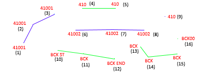
When Line is selected as the layers Intended Use the following will occur:
- Vertices from measurements with the code '41001' are joined in the order they appear in the imported file or database and the line is placed on layer 410.
- Vertices from measurements with the code '41002' are joined in the order they appear in the imported file or database and the line is placed on layer 410.
- Vertices from measurements with the code 'BCK' that are between a 'BCK ST' code and BCK END' code are joined in the order they appear in the file, with the BCK ST and BCK END being the start and end of the line.
- All consecutive points with the code 'BCK' (that are not between a 'BCK ST' and 'BCK END' code) are joined in the order they appear in the file.
- All consecutive points with the code 410 are joined in the order they appear in the file.
- Vertices from measurements with the code BCK00 are not included in the line.
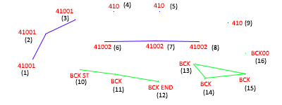
When Polygon is selected as the layers Intended Use the following will occur:
- Vertices from measurements with the code '41001' are joined in the order they appear in the imported file or database and the line is placed on the layer 410.
- Vertices from measurements with the code '41002' are joined in the order they appear in the imported file or database and the line is placed on the layer 410.
- Vertices from measurements with the code 'BCK' that are between a 'BCK ST' code and BCK END' code are joined in the order they appear in the file, with the BCK ST and BCK END being the start and end of the line.
- As there are 3 or more consecutive points with the code 'BCK' (that are not between a 'BCK ST' and 'BCK END' code) they are joined in the order they appear in the file. The last point in the sequence is joined to the first point in the sequence to from a polygon.
- As there are only 2 consecutive points with the code 410 they cannot form a polygon.
- Vertices from measurements with the code BCK00 are not included in the polygon.
- Prior to importing field data, import code libraries to set up layers for stringing.
- If you use string attributes in the field collector, specify the string attribute in the import options.
- String codes entered in the field as an attribute are added to the measurement code on import.
- View or edit the measurement code in the 'Code' column in the measurement view.
- You should only reprocess codes in the Measurement view if line and polygon objects were not imported from the field controller.
- Only some imports support processing of codes.
- Lines and Polygons created in the field collector are imported regardless of the Process Codes settings.
- Clear the Process Codes box on import when codes have been processed in the field and you want to avoid duplication of lines and polygons.
- If modifications to objects on a locked layer is required the entire code processing operation will fail.
- All object types can be place on any layer regardless of the Intended use setting.
- String numbers and control codes will be used to join lines during code processing regardless of the Intended Use set for the layer.
- A "00" string at the end of a code indicates codes of the same type will not be joined regardless of the Intended Use set for the layer.
- You can change the appearance of the object by editing the Appearance attributes.
- If you use Leica free codes to insert control codes the free code should precede the measured point it applies to.
