Show a report that compares selected points to lines.
View / Report / Compare / Points to Lines
- Solve module
- One or more selected points
| Control | Description |
|---|---|
| Title | Type the title to display in the report. |
| Default | Click the button to display the default title for the report. |
| Match vertical |
Select the checkbox to:
|
| Search distances: Horizontal | Type the horizontal offset to search for lines. |
| Search distances: Vertical | Type the vertical distance to search for lines. |
| Tolerances: | Select the checkbox to enable the tolerance boxes. In the report, differences not within the Tolerances display red. |
| Offset Type |
|
| Vertical |
Type the vertical tolerance. Note:
|
| Project start/end segments |
Do one of the following:
|
| Project at external deviation |
Do one of the following:
|
| Use comparison project |
Do one of the following:
|
 |
Browse to the project that contains the lines to compare. |
 |
Move the selected item up in the list. |
 |
Move the selected item down in the list. |
| OK | Show the comparison report. |
| Cancel | Cancel without running the command. |
The following columns are available for output in the report. Select the checkbox to include the items in the report.
| Column | Description |
|---|---|
| Point Name | Name of the compared points. |
| Point Id | Unique Id of the compared points. |
| Point Layer | Layer of the selected points. |
| Point Easting | Easting of the selected points. |
| Point Northing | Northing of the selected points. |
| Point Height | Height of the selected points. |
| Line Name | Name of the Line. |
| Line Id | Unique Id of the line. |
| Line Layer | The lines layer. |
| Line Easting |
Easting of the location on the line where the perpendicular offset to the point is computed. Note:
|
| Line Northing |
Northing of the location on the line where the perpendicular 2D offset to the point is computed. Note:
|
| Line Height |
Height of the location on the line where the perpendicular 2D offset to the point is computed. Note:
|
| Distance |
Distance along the line to the location where the perpendicular 2D offset is computed. Note:
|
| Offset | Two dimensional perpendicular offset from the line. |
| 3D Offset | Three dimensional perpendicular offset from the line. |
| Difference Height |
Difference in height between the height of the line perpendicular to the selected point and the selected point. Note:
|
- Values are from the line to the selected point.
- A negative offset indicates the selected point is to the left of the line.
- A negative height difference indicates the selected point is below the line.
- Only selected points will attempt to have comparison lines located and reported on.
- Only lines that are displayed will be considered for comparison with the selected points, except when a comparison project is specified and all lines within the search distance are reported on.
- Differences not within the specified tolerance are displayed in the report in red.
- When Project at external deviation is selected, display Line Easting, Line Northing and Line Height to display the location where the offset is measured to.
- An asterisks indicates the offset is to a projected line segment .
- Selected columns will be shown in the defined order.
- Press Shift + Ctrl then click to move the column to the top of the list.
- Press Shift + Ctrl then click to move the column to the bottom of the list.
- Only straight segments can be projected at external deviations.
- The average height difference in the reports statistics is the arithmetic mean of the signed values not the absolute values.
| Project start/end segments | ||
|---|---|---|
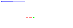 |
 |
Line Projected Line Projected Offset Offset Vertex |
| Project at external deviation | ||
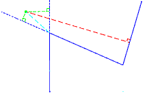 |
 |
Line Projected Line Projected Offset Radial Distance Offset Vertex |
