To complete this tutorial you will require the Input/Output
module.
Note: This tutorial cannot be completed using LISCAD Lite.
Aim
The aim of this tutorial is to show you how to perform a traverse adjustment. You will learn how to:
- Extract traverse observations from a field file into the traverse editor.
- Adjust the traverse.
- Transfer the adjusted results to a LISCAD project.
Typical Scenario
A traverse and detail survey has been carried out using a total station and data recorder. The raw data has been downloaded and a LISCAD field file created. You now wish to extract the traverse observations from the field file, adjust the traverse and save the adjusted co-ordinates of the traverse stations in a LISCAD project. This will enable you to use the adjusted co-ordinates as control when the detail observations are later reduced.
Before you begin
Select this button to obtain the required data file.
Now proceed with the steps below.
- Extract Observations From a Field File into the Traverse
File Editor
Select File/Open and open the file called "Traverse Adjustment.see" in the Tutorial folder. You will see some points and line on the screen that was created previously by importing GPS data.
Select Task/Field Transfer and then select Resolve/Traverses to display the Traverse File Editor.
Select File/Extract and make the selections shown below.
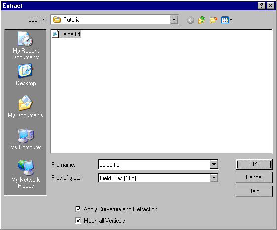
Select OK to produce a report window of the traverse (part of the report is shown below).
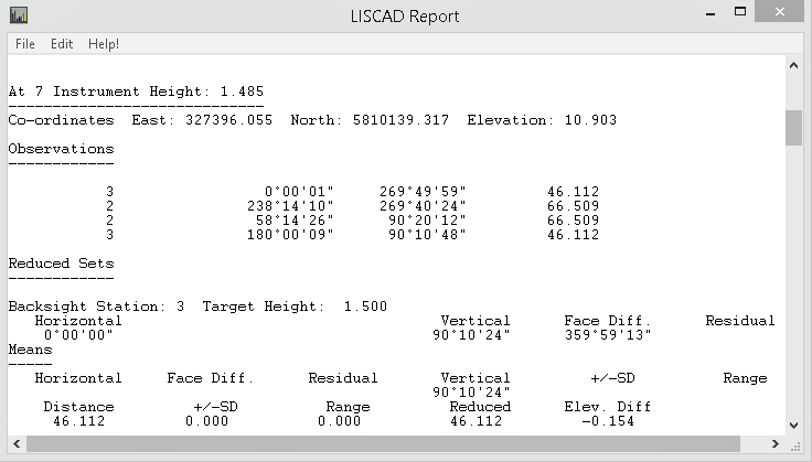
Use File/Print Setup to change the printer settings to Landscape.
Use File/Print to print the report.
Use File/Save As to save the report to a text file.
Then close the report window to see the traverse editor.
To verify that you can see all the relevant columns in the table select View from the menu and ensure that the Angles, Elevations, Co-ordinates, Code, Description and Auto Number menu items are all checked.
If any of the columns in the table contain a series of # symbols (########), click on the vertical dividing line between the column headings and increase the width of the column until the values can be read clearly.
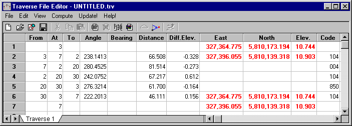
After closing the report window, you will see that the mean angles, mean distances (reduced for slope, earth curvature and refraction only) and mean elevation differences are now shown in the traverse file editor.
You will also see the co-ordinates of point 7 (the first setup point in the traverse) and point 3 (the last setup point in the traverse). Note that these points also provide the orientation control for the starting and closing angles.
You may change the width of the columns by first clicking anywhere in the spreadsheet, and then holding the cursor in the heading row near the column border to be moved. When the cursor changes to an arrow, drag the column border while holding down the Accept mouse button. You may need to do this to see the East and North values which are quite large.
There were actually no co-ordinates entered in the field, so these controlling co-ordinates have not come from the field file. They have been automatically obtained from the "Traverse Adjustment.see" project which has these points with co-ordinates imported from a GPS survey.
Note: Control co-ordinates will be placed into the Traverse Editor in the following order of preference:
- Controlling co-ordinates will always be automatically extracted from the currently open project if the controlling points exist in the project.
- If the controlling points are not in the project, then the co-ordinates will be extracted from the field file if they are in the field file.
- If they are not in the project or in the field file, you may enter them directly to the traverse file editor.
- Adjust the Traverse
Select Compute/Traverse and set the options as shown below.
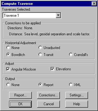
These settings mean that we are going to do a Bowditch traverse adjustment after first adjusting any Angular Misclose, and that we are also going to adjust the Elevations. Note that we have already set the appropriate Corrections earlier. (We will use the default Report and Settings values, but you may like to explore these options at your leisure later.)
Before proceeding, it is necessary to check that the required corrections and earth constants are set. Select the Corrections button to display the Traverse Corrections dialog.
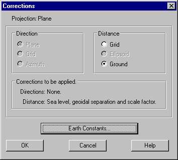
Ensure that Distance/Ground is selected. This ensures that the appropriate distance corrections will be applied when the traverse is adjusted.
Select the Earth Constants button and ensure the settings are as shown below.
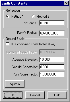
These particular Ground scale settings mean that:
- Sea level correction can be applied to the observed distances using the actual elevations of the end points.
- Any distance that does not have an elevation will be assumed to be at elevation 10 for calculation of sea level correction.
- The geoid and ellipsoid are assumed to be coincident
- The resulting grid distances will be on a plane at elevation zero.
Select OK to close the Earth Constants dialog saving the settings.
Select OK to close the Corrections dialog saving the settings.
Press OK on the Compute Traverse dialog to start the adjustment.
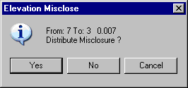
The Elevation Difference Misclose will display as shown. Click Yes.
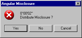
The Angular Misclose will display as shown. Click Yes.
A report window will then display containing a comprehensive report on the adjustment according to the settings made in Compute/Traverse/Report. You may print and/or save the report to a text file, as per the extraction report earlier.
Close the report window. You can now see the traverse file editor with the adjusted co-ordinates.
- Update the Adjusted Co-ordinates into the Data Base
You are now ready to transfer the adjusted co-ordinates to the "Traverse Adjustment.see" project.
Select Update to display the dialog below showing the co-ordinates and elevations in the project (Existing) against the co-ordinates and elevations in the Traverse Editor (New).
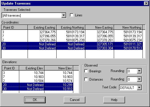
We wish to replace the project values with the adjusted traverse values for only points 20 and 30.
To do this, highlight the rows as shown by clicking them with the Ctrl key held down, then press OK.
Select File/Exit to close the traverse File Editor, and if desired save the traverse file when asked.
Conclusion
You have now completed this tutorial and should have a good understanding of how to perform a traverse adjustment.
You have also learnt how to:
- Extract traverse observations from a field file to the traverse editor.
- Set the appropriate corrections and earth constants for use in the traverse adjustment.
- Perform linear and elevation traverse adjustments.
- Update the currently open project with adjusted co-ordinates and elevations.