To complete this tutorial you will require the 3D Visualisation
module.
Note: This tutorial cannot be completed using LISCAD Lite.
Aim
The aim of this tutorial is to demonstrate how the 3D view within LISCAD operates. It covers the use of textures and how to edit model and triangle attributes. It will also show how multiple models interact with each other in the 3D view.
Scenario
A field survey of an open cut quarry and surrounds has been undertaken. This data has been modelled and some attributes have been applied to the model. A final check of the data has still to be carried out and further editing is required of geometric and attribute data.
We also want to see what the quarry will look like if it was partially filled with water.
Before you begin
Select this button to install the required data files.
NOTE: This tutorial has been designed using the LISCAD default colours. If you have your colours configured differently you will probably find that the display does not match the colours as shown in this tutorial. To change your colours to match this tutorial before opening the file select Utilities / Configure / Colours and press the LISCAD default colours button.
- Open the Example Data File and Configure the 3D Options
 Open the Tutorial file "Opencut 3D.see" by selecting File/Open…
This file currently has 2 views into the data set. Before we open the 3D view we will set some of the configuration options.
From the Utilities Task menu select Configure/3D...
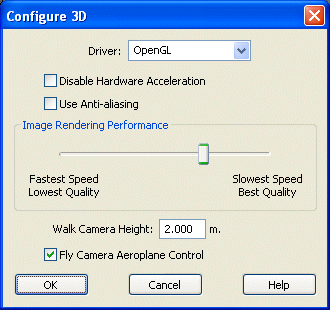
There are three graphics drivers to choose from, OpenGL, WinGDI and Direct3D. If you know that you have either OpenGL or DirectX installed on your computer then select one either OpenGL or Direct3D respectively. WinGDI should work on any computer, but it is only recommended to be used as a last resort as its performance is much slower than the other 2. If you are unsure which driver to use select OpenGL as your default as most modern computers will have this installed.
Do not check Disable Hardware Acceleration unless you find that there are problems with drawing the scene in the 3D view. Turning this on may severely inhibit drawing performance.
Do not check Use Anti-aliasing. Checking this may give some improvement to the rendering of textures at the expense of performance. At a later stage experiment with how the scene appears in 3D with this turned on and off. Only have it checked if you can see a discernable difference and the response time in the 3D view is acceptable.
Set the Rendering Performance at about two thirds of the way towards Slowest Speed / Best Quality.
Set the Walk Camera Height to 2.0 m and have the Fly Camera Aeroplane Control checked.
- Setting Up the 3D View Display
From the main menu select Window. At the bottom of this menu it should say "Plan View" and "3D View". Select 3D View.
Note: If you want to open a new 3D view select Window/New/3D View.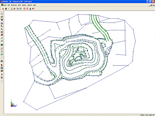
At this stage there appears to be very little difference from the Plan View, except the Toolbar has changed and there is a Axis Triad in the bottom left hand corner of the view. The Axis Triad can be used as a reference to tell you which direction the 3D View is facing.
 To prove that we are in a 3D view place the cursor over the Axis Triad
and hold the left mouse button down. When you move the mouse the viewing
axis of the window will rotate, spinning the data so that you can look at
it from any viewing angle.
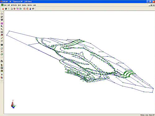
This view offers many different perspectives but it can be confusing with lines crossing over each other and doesn't tell us a great deal more about the job. So lets explore our display options.
Use the
 Display/Plan Fit function to return to the original bird's
eye view.
Display/Plan Fit function to return to the original bird's
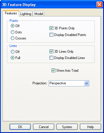
eye view.Select Display/Features to bring up the 3D Display Features dialog. On the Features page turn Points off.
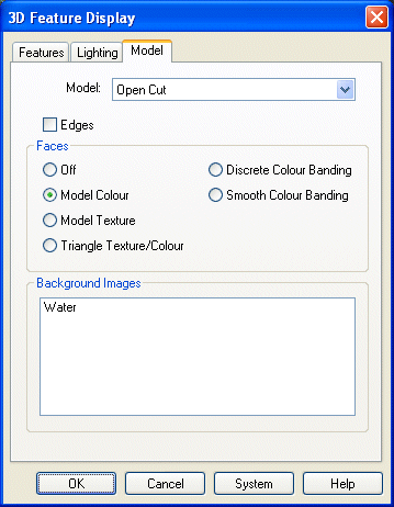
Note: It is on this page that you can turn off the Axis Triad by unchecking Show Axis Triad. However, leave it on for this Tutorial.Now click on the Model Tab to open the Model page. The model should be set to "Open Cut". in the Faces group box select Model Colour.
Click on OK.
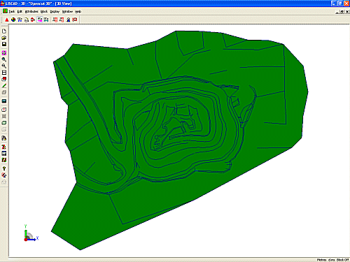
The data now looks solid and you get a better feeling of depth when you rotate the model using the Axis Triad, but the whole thing is very flat. So let's introduce some lighting.
Select Display/Features again to bring up the 3D Display Features dialog and click on the Lighting Tab.
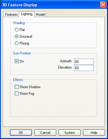
Set the Shading to Gouraud, turn the Sun Position On and set the Azimuth and Elevation to 60. The azimuth and elevation can be set to represent the sun position at a given latitude and time of day.
Click on OK.
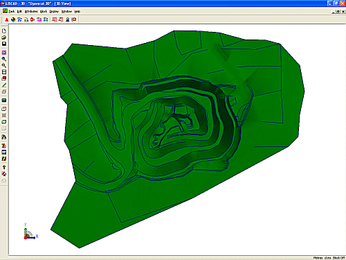
This gives the model a much greater feeling of depth and also smooths out the gentle changes of grade over the model triangles.
However the model is not quite as solid as it might appear. If you use the Axis Triad to rotate the model so you are looking under the model you will find that the model is transparent underneath.
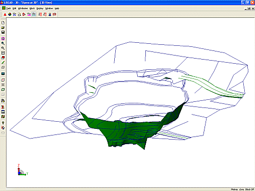
This may also be disconcerting as any triangles facing away from the observer are transparent, whereas any triangles facing the observer appear solid. This can sometimes lead to confusion.
To view both sides of the model select Edit / View/Edit Model Attributes.
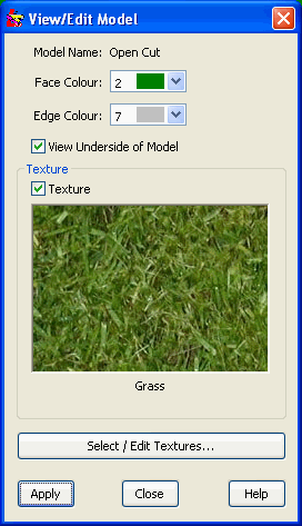
Snap to and accept the model. Check View Underside of Model and click on Apply.
The reason this can be turned off is for performance reasons. If you have a large model and you will only be observing it from the top side there is no need for the graphics engine to have to try and render both sides of triangle faces and so the performance is greatly improved. In this case the data set is small and so you should be able to view both sides of the model without any noticeable loss in performance.
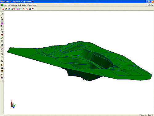
Now let's look at other ways we can display the model.
Select Display/Features - Model Tab and select Model Texture on the "Open Cut" model. Click OK.
The model will now be displayed using a Grass texture, which had been previously assigned to the model.
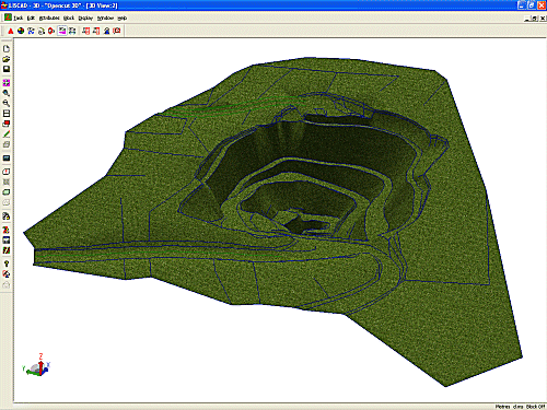
This is a quick way of getting a more realistic rendering of the entire model. A texture is a small bit map that when tiled forms a seamless image. Texture bitmaps are scaled by a user defined ground width.
Now select Display/Features - Model Tab again and select Discrete Colour Banding on the "Open Cut" model. Click OK.
The model will now be displayed divided up into colour bands based upon the height range in the data set.
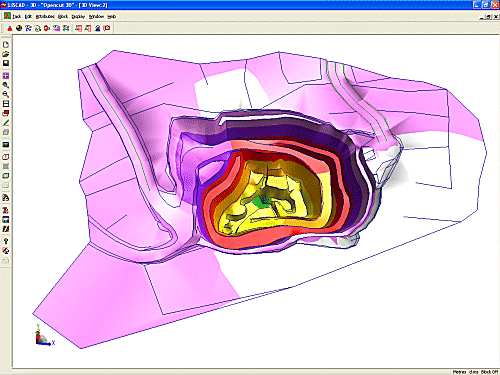
Now select Display/Features - Model Tab again and select Smooth Colour Banding on the "Open Cut" model. Click OK.
This is the same as the Discrete Colour Banding, except the colours are merged into each other, rather than suddenly changing.
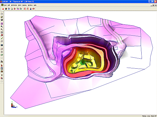
Now select Display/Features - Model Tab again and select Triangle Texture/Colour on the "Open Cut" model. Click OK.
This is the best way of artificially rendering the surface of the model as each triangle has been assigned its own colour and or texture. If a triangle has been assigned both a colour and a texture the texture will always be used in preference to the colour. In this data set every triangle has been assigned a texture.
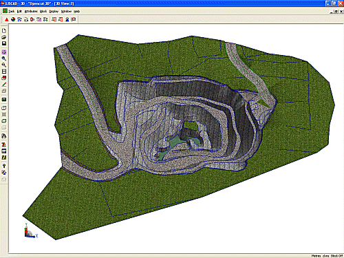
- Navigating Around the Model
We have already looked at using the Axis Triad to rotate the model and the Plan Fit function to return to the bird's eye view.
Note: The Plan Fit function is always good to use if you become lost or disoriented. From here you can always quickly return to the place where you wanted to be.The 3D view has 5 different cameras to allow you to view and navigate around the model in different ways. We will examine each of these cameras in turn and look at some of the common functionality they all share.
 Walk Camera - (Display/Walk Camera)
This camera allows you to emulate walking or driving around the model. When you start walking the camera positions itself above the model at the Walk Camera Height you have set in the Configure 3D dialog, in this case 2.0m.
Select the Display / Walk Camera. To get started double click on a part of the model you want to go to. This will take you to that point and set the camera up at 2.0m above the model.
Note: The double click works with all the cameras and can be used at anytime to quickly get you to a point of interest.Start by double clicking somewhere on the grass near the edge of the open cut quarry.
Now before you start walking orient yourself so that you are facing in the direction you want to go. To do this hold down the Shift Key on the keyboard and the Left Mouse Button. If you move the cursor to the left you will look left, move it right and you will look right. Similarly you can look up and down by moving the cursor in those directions. The further you move the cursor the faster you will turn in those directions. On the status bar you can see the direction that the camera is pointing and your angle of elevation or depression.
Also on the Status Bar is a speed display. This is either in Km/Hr. or Mi/Hr. depending upon the speed display that is set in Utilities / Configure/Alignment... When you first select the walk camera the speed will default to 5 Km/Hr or 3 Mi/Hr. You can increase the speed by pressing or holding down the + (plus) key on the keyboard and you can decrease the speed by pressing or holding down the - (minus) key. The speed you set will be remembered when you return to the Walk Camera during this session.
To start walking simply hold the left mouse button down. Move the cursor to the left or right to move in those directions. The further you move the cursor the more rapidly you will turn. You can also look up and down when walking by moving the cursor up and down. Keep the cursor in the centre of the screen to keep moving straight ahead without deviating.
Try walking around the top of the quarry without "falling in". Keep the speed low while you get the feel of the controls and if you loose direction just stop and hold the shift key down to look around and orient yourself. If you get totally disoriented use the Plan Fit function and double click to get yourself back to where you want to be.
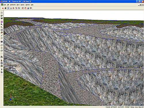
When you are feeling more adventurous try walking down the haul roads into the quarry.
Another function that can be used with all cameras is the ability to zoom in and out by stepped increments. If your mouse has a wheel, rolling it forward zooms you out and rolling it back zooms you in.
Note 1: If you zoom out, depending upon where you are and where you are facing, you can go backwards through the surface on the model and find yourself underneath the model, disorienting yourself.
Note 2: If you are using the Walk Camera and you zoom in and out along the line of sight you will no longer be at your nominated height above the model. When you start walking again the camera will position itself at the correct height above the model once more.Like the Pan, Window and Zoom functions in Plan view you can click the right mouse button to cancel out of any of the cameras.
 Fly Camera - (Display/Fly Camera)
This camera allows you to emulate flying around the model. The Fly Camera controls are set depending upon what you have set in the Configure 3D dialog, in this case we have set Fly Camera Aeroplane Control to be on.
Using the Fly Camera Aeroplane Control the mouse acts like a joystick. If you pull the mouse towards you while holding down the left button it is like pulling back on a joystick and you will climb. Push forward on the mouse and you will dive. Moving the mouse to the left or right will cause you to fly in that direction and the scene will bank into the turn. When the mouse is in the centre of the view the camera will fly straight ahead on an even keel.
If the Fly Camera Aeroplane Control is off the Fly Camera will follow the mouse, so if you move the cursor up the screen you will fly up, move the cursor down and you will fly down. How you have the control set is a matter of personal preference. Try them both and leave it set for the one that you feel most comfortable with.
You start flying from the current camera position and in the direction you are facing. If you want to go to a particular spot you can double click the left mouse button to take you there, just like the Walk Camera.
Perform a Plan Fit then select the Fly Camera.
From this position you would be flying straight down into the quarry. To orient the camera so that you are flying parallel to the ground double click on an area close to the edge of the model. Now holding down the shift key turn the camera around so that you are facing the direction you want to fly.
On the status bar you should be able to see the speed you will be travelling. The first time you use this function in a session a speed is calculated based upon the size of the data set. You can use the + (plus) and - (minus) keys to increase or decrease the fly speed. While you are getting the feel of flying keep the speed low. A speed of around 20Km/Hr. would be good to start with.
Practice flying horizontally from one side of the model to the other down into the quarry and up the opposite side. Then to practise turning try flying around the inside top of the quarry.
It may feel strange at first, but it will soon start to feel natural. Avoid sudden large moves and try not to concentrate on the cursor, fly by feel rather than focusing on the cursor. If you get completely disoriented use the Plan Fit and then reposition yourself where you want to be. Don't worry if you hit the ground it won't hurt too much!
 Orbit Camera - (Display/Orbit Camera)
This camera allows you to rotate the model around the centre of the view. It works similarly to moving the Axis Triad.
Select the Orbit Camera and holding the left mouse button down to rotate the model. Try moving to different positions and then use the Orbit Camera to control the scene.
 Zoom Camera - (Display/Zoom Camera)
This camera allows you to smoothly zoom in and out from the model, unlike the mouse wheel which zooms in stepped increments.
Select the Zoom Camera and holding down the left mouse button, move the cursor up the screen to zoom in and down the screen to zoom out. Again try moving to different positions and then use the Zoom Camera to control the scene.

 Pan Camera - (Display/Pan Camera)
This camera allows you to smoothly pan around the model.
Select the Pan Camera and holding down the left mouse button, move the cursor in the direction you want to pan the scene to. Again try moving to different positions and then use the Pan Camera to control the scene.
Other Techniques for Manipulating the View
 Fit - (Display/Fit)
This function works differently to a Plan Fit. Effectively it zooms out from your current view position so that you can see the entire model.
 Zoom In - (Display/Zoom In)
This function works similarly to the Plan View. It centres the view on the position you click the mouse and zooms in by a factor of 2.
 Zoom Out - (Display/Zoom Out)
This function works similarly to the Plan View. It centres the view on the position you click the mouse and zooms out by a factor of 2.
 Window - (Display/Window)
This function works similarly to the Plan View. It zooms in on the scene selected to fit the 3D view window.
 Pan - (Display/Pan)
This function works exactly the same as the Pan Camera.
- Editing the Model Rendering
On the Display/Features - Model Page make sure that Edges is checked and that the Triangle Texture/Colour has been selected. The triangle edges are displayed in a light grey colour, (if you have LISCAD configured for its default colours), which does not show up against the grey rock of the quarry very well. First we will change them to a colour that stands out better against this model.
Select
 Edit / View/Edit Model Attributes, click on
to the model and change the Edge Colour to Black (0) and click
on the Apply button.
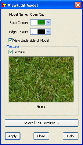
Click the Close button.
Perform a Plan Fit.
On the right hand side of the model you will notice a single triangle near the top of the quarry that has a "Grass" texture where it should be "Pavement".
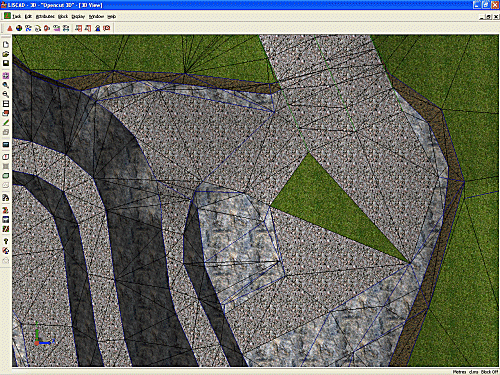
To change this to "Pavement" select
 Attributes / Adopt Triangle Attributes. Click on one of the
surrounding triangles that has the "Pavement" texture.
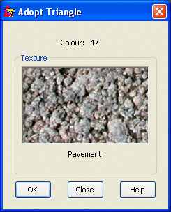
Click the OK button and Close the dialog box.
Select
 Edit / Edit Triangle Attributes. Check both Colour
and Texture and then click on the triangle you want to change.
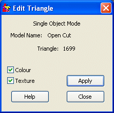
Click Close.
This technique works well for individual triangles, but would require a lot of clicking if there were many triangles that required to be changed to the same colour and texture. Let's perform this function again on a Block of triangles.
Perform a Plan Fit. In the centre of the model near the bottom of the quarry there is a group of triangles with the "Grass" texture that should be "Rock". Window in on these triangles.
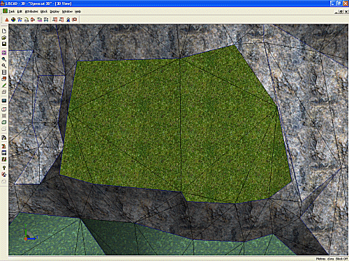
To change this to "Rock" select
 Attributes / Adopt Triangle Attributes. Click on one of the
surrounding triangles that has the "Rock" texture.
Attributes / Adopt Triangle Attributes. Click on one of the
surrounding triangles that has the "Rock" texture.Click the OK button and Close the dialog box.
Select the
 Block / Freehand function.
On the Block dialog box set the Shape to Free Form, the Region to Inside and the Condition to Enclosed. Click Define.
You can now click around the triangles that need changing until you click back on your starting point. This will cause the selected triangles to highlight and the Block will turn off.
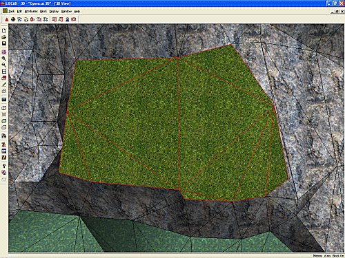
Note: Unlike the Plan View, while you are in the process of defining a Block, you cannot use any of the view manipulation functions in the 3D View like, Fit, Zoom etc. or any of the Cameras. This is because in 3D the perspective will change if you use any of these functions which will change the relationship of the Block which is a 2 dimensional object in the plane of the screen. If you attempt to use any of these functions before closing the Block the Block formation will be terminated. Once the Block has been closed and the triangles have been highlighted you can once again use the view manipulation functions and the triangles will remain highlighted.
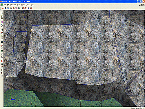
Now select
 Edit / Edit Triangle Attributes. Make sure both Colour
and Texture are still checked and then click on the
Apply button.
- Creating a New Texture
There is one other area where the triangle faces need editing. In the top left corner of the quarry there is a section of loose rock that has fallen down as a result of the excavation work. We will edit the faces of these triangles with a texture that is more appropriate.
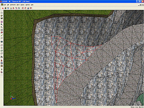
(The triangles have been highlighted to show the area we want to change.)
In this case we do not have a suitable texture within the model that we can adopt so we will have to create a new one.
Select Attributes / Set Triangle Attributes from the menu. Then click on the Select / Edit Textures button.
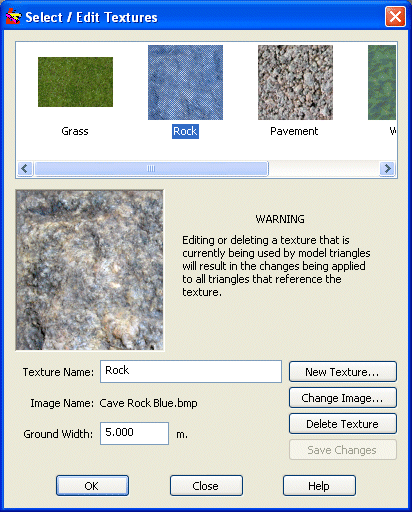
Click on the New Texture button. This will open up the Open Image dialog which will allow you to navigate to the required image for the new texture. Find the image "Rock.jpg" and select it. The dialog will close and the image will be transferred to the Select / Edit Textures dialog. At the same time it will also create a Texture Name of "Rock" from the Image Name. We already have a texture called "Rock" so edit the Texture Name to "Loose Rock". All that is needed now is to enter a Ground Width for the image. A value of 5m should look good.
Click the Save Changes button to transfer the new texture into the list of textures at the top of the dialog.
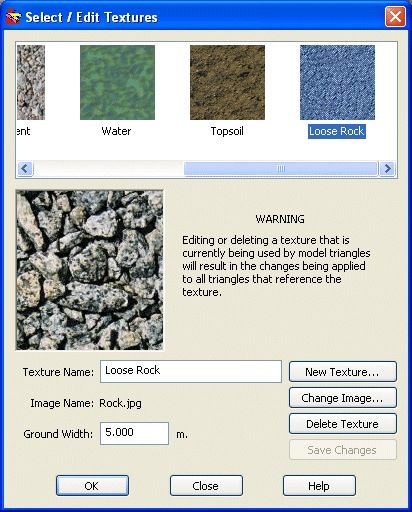
Make sure that the "Loose Rock" texture is selected and click OK.
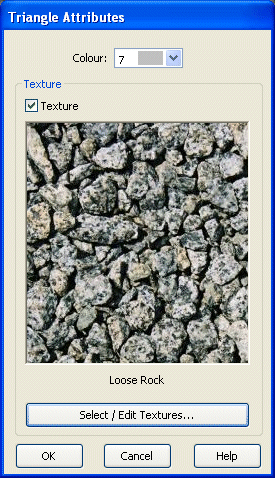
Click OK.
You can now use Edit Triangle Attributes to edit the triangles individually by clicking on them or by editing them all simultaneously by using a Block as we did earlier.
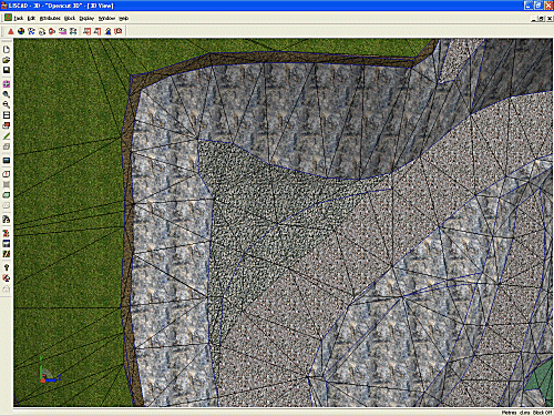
This finishes off the editing of the triangle faces. Now we will look at problems with the geometry.
- Editing the Model Geometry
After looking at the model in 3D it has now become clear that there are some problems with the geometry that were not apparent in the Plan View. The bottom of the quarry is represented by the water level, which should be flat, however if you go down into the model or perform a Plan Fit and then use the Orbit Camera to tilt the model on its side it soon becomes apparent that the water is not level. There is a spike on the bottom.
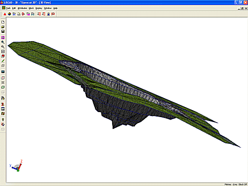
To determine what is the problem switch back to the Plan View by selecting Window / Plan View.
Window in to the base of the quarry and use
 Display / Features to turn on the Point Identifiers
and Elevations.
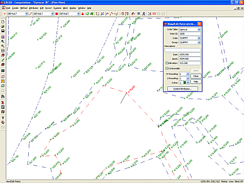
 Point 1000 has an error in elevation of 10.000m. The current elevation is 405.280 and all the other points in the line have an elevation of 415.280.
Use
 Task / Computations / Edit / View/Edit / Points to edit the elevation
of point 1000 to 415.280.
Now use Window / 3D View to return to the 3D View and you will see that the 3D model has been automatically updated.
Further examination also reveals that an area to the south of the quarry near the top also does not look right. This area was a bench, but now has a mound on it and drops away at one point to the path below it.
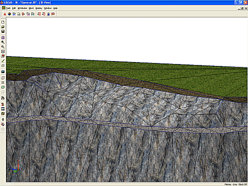
Return to the Plan View to see what the survey looks like.
Window in to the area.
The problem is caused by two missing breaklines. There should be a breakline running from point 1076 through 166, 167, 168, 169 and terminating at 1077. There should also be another breakline running between points 1076, 74, 75, 76, 77, 78, 79, 80 and 1077.
We could join the points up with breaklines and then form a new model, but then we would loose all the texture editing we have already completed. There is another way that we can modify the model without destroying all our earlier work.
Select Display / Features - Model Tab and turn on the triangles.
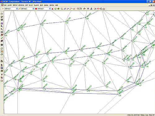
Now select Task / Terrain Modelling and then select Edit / Flip Triangle. This will change the cursor to the shape of two triangles. Now when you click on a common side of two triangles the common side will flip to the opposite apex points of each triangle.
Click on the following common lines between triangles, in order, to flip them so that the triangles look like the next picture.
Points 736 to 169; then
Points 79 to 3191; then
Points 735 to 167; then
Points 75 to 1069; then
Points 733 to 3193; then
Points 733 to 166; then
Points 77 to 3193; then
Points 78 to 3192; then
Points 78 to 3193.Exit the
 Flip Triangles command by pressing the ESC key or selecting
another command.
Flip Triangles command by pressing the ESC key or selecting
another command.If you wish to add the breaklines as well you can do this by using the
 Create Lines by Existing Points function in Computations.
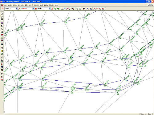
Now return to the 3D View and the model now looks correct.
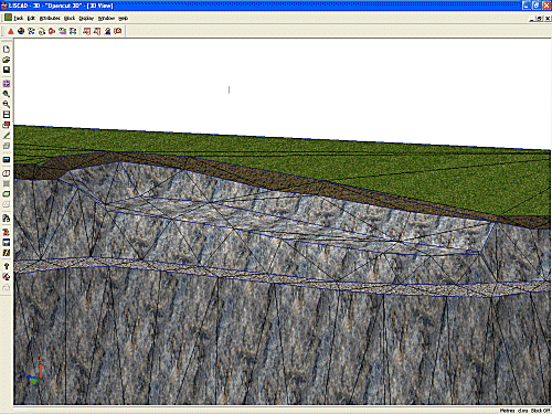
- Adding a Second Model
We will now create a model representing the water level so that we can see what the quarry will look like if it is filled.
Return to the Plan View and select Display / Features. On the Points page turn OFF Identifiers. On the Model page turn off Triangles. Now set both the Minor and Major Contour Intervals to 455.0 and turn ON Contours. Click OK.
Now select Display / Groups and turn off all the groups. Click OK.
All that should be displayed is the 455.0 m contour. This line represents where the 455.0 m plane would intersect the model of which the closed section would represent the water level on the quarry.
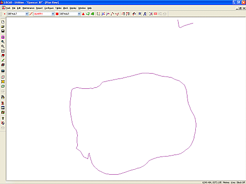
We will now place some points around the outside of the closed contour.
Select the "WATER" point code from the Point drop down code list. This will ensure that the points we create are on a separate group. Now from the Computations Task select Create Point by Freehand. Set the elevation to 455.0 and place points close to the outside of the contour around the edge at an interval that will guarantee that when we create the model it will fully cover the area, but not to excess.
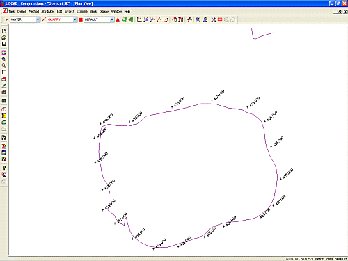
Now from the Terrain Modelling Task select
 Modelling / Form Model and create a model from these points
called "Water Level".
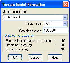
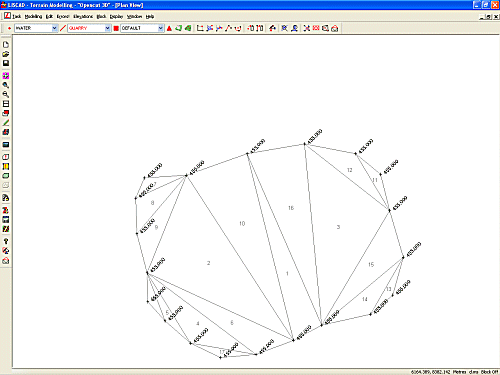
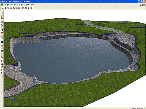
Now switch back to the 3D View by selecting Window / 3D View. Select Display / Features and go to the Model page. The drop down list now contains 2 models, "Open Cut" and "Water Level". With "Open Cut" selected turn OFF Edges. Now select the "Water Level" model and in the Background Images list click on "Water". "Water" is a background image that is an aerial photograph of a body of water which was registered earlier, but was not displayed in the Plan View. By selecting the "Water" background Image in the 3D view it will drape it over the surface of the selected model.
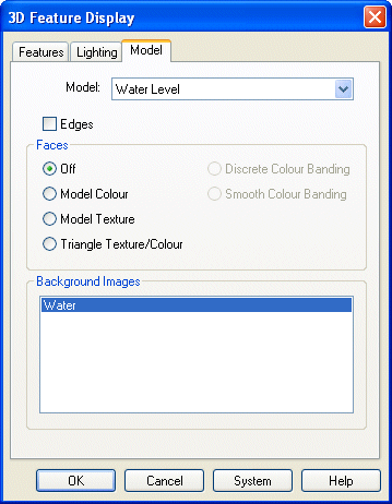
Click OK. Your 3D View should now look like this.
Conclusion
You have now completed the Introduction to the 3D View and should have a good understanding of the following:
- Configuring the 3D drivers;
- Controlling the display of objects in the 3D view;
- The different ways that model surfaces can be rendered;
- How the cameras work and how you can control where you are and where you wish to look;
- Creating new textures and editing existing textures;
- Editing triangle faces;
- Editing triangle geometry without destroying the model;
- Displaying more than one model simultaneously in the 3D view;
- Draping background images over the surface of a model.