To complete this tutorial you will require the Input/Output module.
Aim
The aim of this tutorial is to show you how to reduce a field file, creating points and lines in a currently open project. You will learn how to:
- Set the required code definition to match the feature code structure used in the field.
- Set the appropriate corrections, earth constants and reduction options to ensure the required corrections are applied in the reduction process.
- Use an appropriate code table and lookup table to ensure that the feature codes used in the field are interpreted as desired and required point and line attributes are automatically allocated.
- Use display commands to control the graphics display of the reduced objects.
Typical Scenario
A traverse and detail survey has been carried out using a total station and data recorder. The raw data has been downloaded and a LISCAD field file created. The control points for the detail survey have already been extracted, adjusted and transferred to the appropriate project. You now wish to reduce the detail observations into that project creating the appropriate points and lines.
Before you begin
Select this button to install the required data file.
Now proceed with the steps below.
- Set-up the Code Definitions
Select File/Open and open the file called "Field File.see" in the Tutorial folder. You will see some points and lines on the screen that were created previously, by importing GPS data, and by transferring adjusted traverse points in from the traverse file editor. Hence the project already contains the setup and orientation points used to collect the detail observations in the field.
Before reducing a field file, you must first ensure that LISCAD is set to interpret the feature codes contained in the field file correctly. To do this, select Task/Field Transfer and then select Settings/Code Definition.
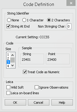
The feature coding system used in the field was 3 digit numeric codes with 2 digit string identifiers at the end (CCCSS). Hence make the settings as shown.
Under String Identifier, select:
- 2 characters
- String At End
- Non Stringing Char 0
Under Code, select:
- Size 3
- Treat Codes Numeric
Select OK
- Reduce the Field File
Select Resolve/Reduce Field File to display the Reduce Field File dialog.
Before proceeding with the reduction, it is necessary to check that the required corrections and earth constants are set. Select the Corrections button to display the Corrections dialog.
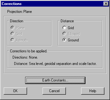
Ensure that Distance/Ground is selected. This ensures that the appropriate distance corrections will be applied when the field file is reduced.
Select the Earth Constants button and ensure the settings are as shown below.
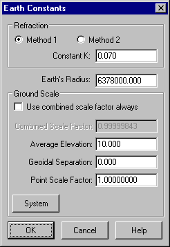
These particular Ground scale settings mean that:
- Sea level correction can be applied to the observed distances using the actual elevations of the end points.
- Any distance that does not have an elevation will be assumed to be at elevation 10 for calculation of sea level correction.
- The geoid and ellipsoid are assumed to be coincident
- The resulting grid distances will be on a plane at elevation zero.
Select OK to close the Earth Constants dialog saving the settings.
Select OK to close the Corrections dialog saving the settings.
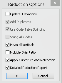
From the Reduce Field File dialog, select the Options button to display the Reductions Options dialog and make the selections shown.
These settings mean that any multiple vertical observations will be averaged for reduction and that C&R correction will be applied.
Select OK to save the settings and close the Options dialog. This will return control to the Reduce Field File dialog.
Make the selections in the Reduce Field File dialog as shown below.
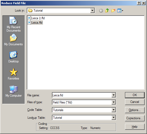
"Leica.fld" is the field file containing the detail observations.
The Code table "Tutorials" contains the codes that we wish to use in the LISCAD project.
Note that the codes used in the field file were different to those in the "Tutorials" code table. To overcome this, the "Tutorial" lookup table is also selected as this lookup table matches the codes used in the field to appropriate codes defined in the tutorial Code Table.
Select OK to reduce the field file.
The reduction is performed and a report window displayed.
Note in particular the duplicates part of the report, which is providing the co-ordinate differences between multiple calculations of the same point position. As Utilities/Configure/Point Identifiers is set to Unique, only the first occurrence of a particular point is stored. If a point is already in the project, its co-ordinates remain unchanged, otherwise the first calculation of the co-ordinates from the field file is used.
You may print or save this report to a text file. Then close the report. You can now see the reduced data on the screen.
- Reduce a Second Field File
Repeat step 2, but this time reduce "Leica 2.fld".
This is a field file resulting from additional fieldwork done later. This process demonstrates how you can process multiple field files into the same project, allowing you to build the project day by day until the fieldwork is completed.
In the reduction report, note the blunder in the observation to Point 4. This highlights the benefit in always inspecting the reduction report. In this particular case, do not be concerned, as we have deliberately introduced the faulty observation to highlight this duplicate-reporting feature. The co-ordinates of point 4 were already correctly in the database and the bad observation is therefore being ignored by the system.
- Set-up the Display Features
Select Display / Features and then select the Points tab.
Turn off the Identifier check box and the Description check box.
Select the Features tab and turn on the Use Colour Number check box.
Select OK to close the dialog.
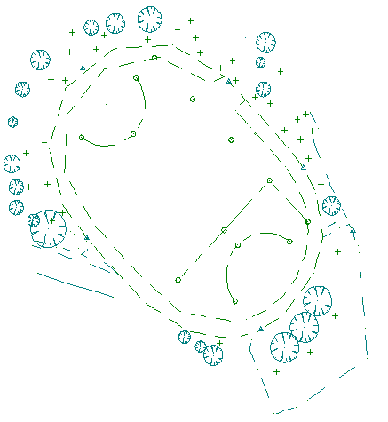
Select Display/Fit (or the fit tool) to fit the data to the graphics window and redraw the data without the point identifiers and descriptions, and in the object pen colours, as per below.
Conclusion
You have now completed this tutorial and should have a good understanding of how to reduce field files.
You have also learnt:
- There is a strong relationship between the feature code, entered on the total station, and the code stored within the LISCAD code table.
- If the feature code used in the field is different to the coding that you want to use in LISCAD, then a Lookup Table can be used at the time of reduction to translate the field code into the required code. In the tutorial we have used a lookup table to translate a numeric field code to an alpha code for use in the office.
- Lookup tables can also be used to translate codes when exporting to other systems.