To complete this tutorial you will require the Computation and Input/Output modules.
Aim
The aim of this tutorial is to show you how to perform basic Computations tasks involved in editing lines picked up in the field. You will learn how to:
- Break lines
- Create lines
- Join line strings
- Create splines
- Join existing points with lines
Typical Scenario
You have a project but not all of the capabilities of the LISCAD field coding and operation coding were used in the field. As such, the objects created in the project need some editing to obtain the desired result.
Before you begin
Select this button to obtain the required data file.
Now proceed with the steps below.
- Locate a Specific Point in the Data Set
Select File/Open and open the file called "Line Edit.see" in the Tutorial folder.
Select Task/Computations and then select Examine/Find/Point.
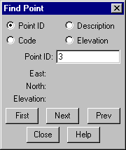
Select the Point ID radio button. Click in the Point ID field and type 3. Then click the First button.
You will notice that the system locates and rubber bands to point 3.
Close the dialog, and then use Display/Window (or the Window tool) to obtain a closer view the area around point 3.
- Delete Unnecessary Line Segments
We now want to delete segments out of lines that have been inadvertently joined in the field survey.
Select Edit/Break Line.
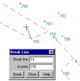
Use right mouse button to snap to point 155, and the line passing through this point will highlight.
Select the Break button, to divide this line string into two components contiguous at point 155.
Repeat this process to also break the lines at points 154 and 100.
Select Close.
Select Edit/Delete/Lines
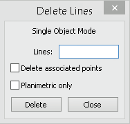
Snap to the line segment between points 154 & 155.
If correct line is highlighted, select Delete. Ensure that you DO NOT delete the associated points.
Use above process to also delete the line between 4 & 100.
Select Close.
- Connect and Join Broken Lines
You now need to create some new connecting lines, but first you should set the required attributes that the new objects are to be created with.
Select Attributes/Adopt/Line & Point
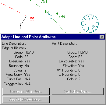
Snap & accept point 155 to set the correct line and point attributes for the line to be created. (EB)
Close the dialog box.

Note the change of codes in the code lists to those of the point and line adopted.
Select Create/Line and then select Method/Existing Points.

Snap and accept point 154, followed by point 3, then select End to create a line between these points.
Snap and accept point 155, followed by point 100, then select End to create a line between these points.
Select Examine/Find/Point as in step 2, but this time find point 2.
Repeat step 6, but this time create lines between 163 & 116, and then 143 & 12.
Note: Points 2 and 12 are very close together. Ensure you snap and accept point 12, not point 2 when creating the line from 143 to 12.
Select Edit/Join Line/By Point
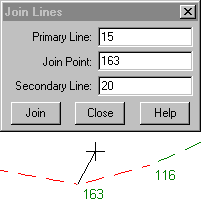
Snap and accept point 163, noting that the major string is highlighted.
Snap to point 163 again and accept if the small line segment between points 163 & 116 is highlighted, if not snap again until it is, and then accept. This will join the two lines meeting at point 163 into a single line object.
Repeat this process to join the lines at each of the following points.
- 116
- 143
- 12
- 154
- 155
Close the Join Lines dialog.
Select Display/Features and then the Points tab. Turn off Identifiers and then select OK.
Tip: You can quickly show the Display Features dialog by right clicking anywhere on the screen and selecting it from the floating menu. Select Display/Fit (or the Fit tool)
Tip: If the job you are working with has a large number of points, this may cause the job to take a while to redraw. You can stop a job redrawing at any time by right clicking anywhere on the screen.
- Convert Some of the Line Types
Select Edit/Objects/Line to Spline
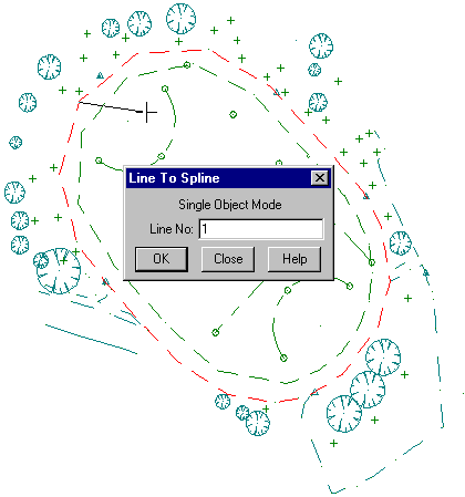
Snap and accept the string on the outside of the track to change it to a spline.
Snap and accept the string on the inside of the track to change it to a spline.
Close the dialog.
Parts of this spline are not appropriate to be curved. These are going to be cut out of the spline and converted back to a straight line object.
Select Examine/Find/Point to find point 103.
Select Display/Window (or the Window tool) to window in around this area.
Select Display/Features and the Points tab. Turn on Identifiers and select OK.
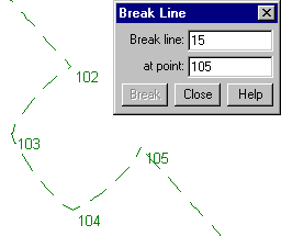
Select Edit/Break Line.
Snap and accept point 102 to break the spline at that point.
Snap and accept point 105 to break the spline at that point.
The picture shows how the data should look after these actions.
Close the dialog
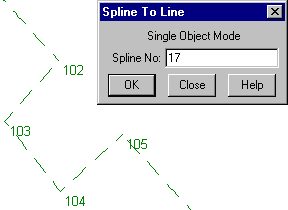
Select Edit/Objects/Spline to Line.
Snap and accept the spline defining the edge of the pit near point 103, to change this spline back into a line.
The picture shows how the data should look after this action.
Close the dialog
Select Display/Fit (or the Fit tool).
- Import Further GPS Field Data
There is still some further data to be imported from a GPS survey of some of the points for the side of the sports ground.
Select Task/Data Conversions and then Import/SKI-GPS.
Note: If SKI-GPS does not appear on the Import menu, select Import / Add/Remove and select SKI-GPS from the Available list by double clicking on it to add it to the Installed list. Close the Add/Remove dialog box and SKI-GPS will now appear on the Import menu.
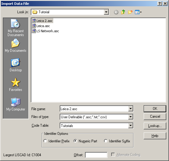
Make the selections shown below and select OK.
Make sure you enter 2000 in the Offset field to avoid clashes with point identifiers already in the project.
- Clean up the New Field Data
Select Task/Computations and then Attributes/Adopt/Line & Point.
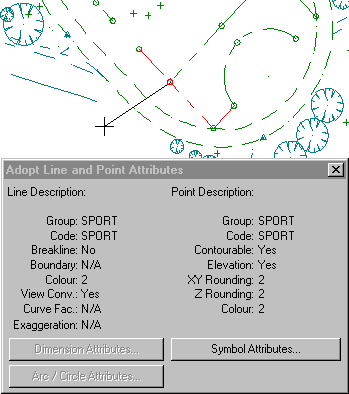
Snap and accept any point defining the edge of the sports field, as shown above, setting the point and line codes to SPORT.
Close the dialog.
Select Create/Line, by Method/Existing Points.
Snap and Accept the points (or key in the point numbers followed by OK), then press End, to create the additional lines between the following points.
2019, OK, 782, OK, 780, OK, 783, OK, 800, OK, 801, OK, 730, OK, End
2026, OK, 2022, OK, End
721, OK, 718, OK, 720, OK, End
Close the Create dialog.
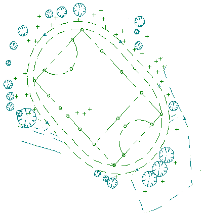
The project should now appear as shown below.
Conclusion
You have now completed this tutorial and should have a good understanding of Line editing in the Computations module.
You have also learnt how to:
- Find points.
- Use the Window tool
- Break lines, so that segments can be deleted
- Delete lines
- Adopt attributes of existing points and lines
- Create new lines
- Join lines to make a single line object
- Display different features
- Use the Fit tool
- Edit lines to become splines
- Edit splines to become lines
- Import additional data into an existing project.