To complete this tutorial you will require the Adjustment module.
Note: This tutorial cannot be completed using LISCAD Lite.
Aim
The aim of this tutorial is to show how a traverse network is adjusted using the least squares adjustment method.
Typical scenario:
At the start of this project we have been given the data (local co-ordinates) on a number of main points surrounding the area of new development.
We will need several more stations to serve as a base for future stake-out operations.
The locations of the extra points have been determined from drawings of the design in such a way that we will always have sufficient visible references.
Since the ground at the site is still being levelled, we do not yet have elevations for the points.
Before you begin
Select this button to obtain the required data files.
- Import the Control Points
First we need to enter the co-ordinates of the known stations into a new project:
Select File/New to create a project on a Plane datum. Enter an appropriate job name: e.g. "Least Squares Network".
Next select Display/Features and on the Points tab set tick marks at Identifier and Crosses.
Press OK.
Next the three known stations must be created in the database. Fortunately they were made available in an ASCII file named: "LS Network.asc". We only need to import this file into SEE.
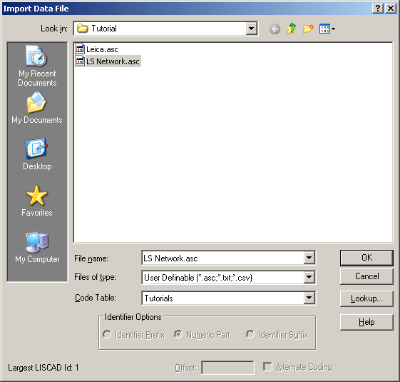
Select Task/Data Conversions - Import/User Definable.
If User Definable is not on the menu select Import / Add/Remove to install User Definable on the Import menu.
In the Data Import File dialog browse to the Tutorial folder and select file: "LS Network.asc".
Now the User Definable Import dialog opens. Make the settings as shown below:
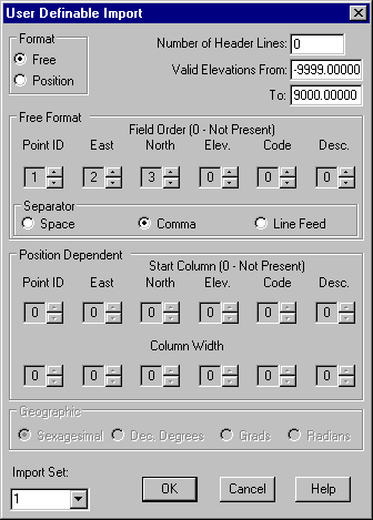
Select OK to start the import of the known stations.
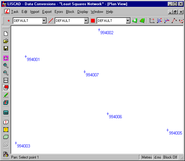
Upon completion of the import there will be an error flagged, caused by the station data to not contain object codes. Ignore this error by pressing Cancel.
The points will be shown on the screen.
- Extract the Field Data into the Least Squares Adjustment
Editor
The survey data has already been downloaded and is available in field file: "Network.fld".
Select Task/Adjustment - Adjustment!
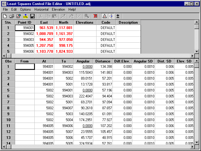
This opens the spreadsheet editor for the adjustment data.
There are two screen sections visible. The upper section is used for entering and examining known and calculated co-ordinates. The lower section holds all observation data. The sections can be switched on or off individually using the tools Stations and Observations in the toolbar or by selecting Options/Station and Options/Observation from the menu.
Before the network adjustment process can be started, we need to import the observation data into the spreadsheet. During the import process the co-ordinates of any referenced stations will be extracted from the LISCAD database and will automatically show up in the upper section of the spreadsheet.
Select File/Extract and double on the "LS Network.fld" file.
All available data will be placed into the spreadsheet.
- Tell the System What Type of Observations it is Dealing
With
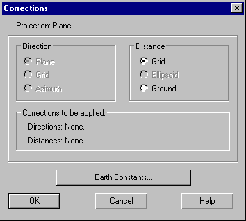
Next we need to set the proper corrections for the adjustment.
Select Horizontal/Corrections.
Make sure that Distance - Grid has been selected. This effectively disables any special corrections. This is consistent with working in a local co-ordinate system.
- Compute the Approximate Co-ordinates of the Unknown Points
Before we can continue, we need to have preliminary co-ordinates for all stations referenced by the observations.
Determine preliminary co-ordinates by selecting: Horizontal/Approx. Co-ords.
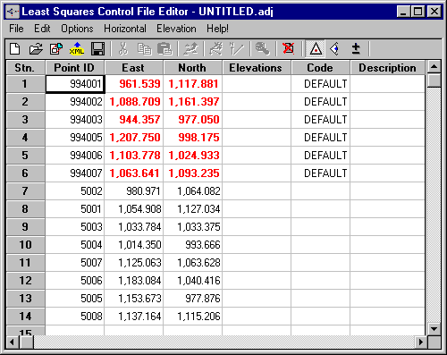
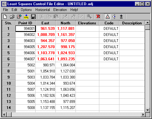
Note that the known station co-ordinates will be shown in red and the preliminary co-ordinates are in black.
In this tutorial we need not adjust the heights as these are not available.
In situations where heights need to be adjusted as well, you can opt to adjust heights in tandem with the adjustment of the horizontal. However, if you expect relatively large adjustments or are not sure of the quality of your network data, it is often advisable to postpone adjusting the heights until the horizontal adjustment has been fully completed.
- Check the Horizontal Observations for Gross Errors
The next step consists of a validation of the network; select Horizontal/Check.
This will display a report detailing the validation results.

Since several excessive errors are indicated, this means there must be something seriously wrong.
- Track Down and Correct the Gross Errors
Let us examine the report and try to establish the source of the error.
In general we can expect two kinds of errors:
- Observational errors
- Errors in known stations
Normally the odds are in favour of errors made in observations.
Most errors in observations will cause the observations to be flagged for either direction or distance.
In the error report we just produced several lines are flagged, that seem to have little relation to each other.
Also the amount of flagged lines is larger than a good survey should yield.
One should be aware how the preliminary results in this check have been determined. First the preliminary co-ordinates were calculated by simple traversing in the order of the observations. The observations are then checked by doing a preliminary adjustment.
Keeping the above in mind while evaluating our results, we find the largest errors are in observations from points 994006 and 994005. Normally our first impulse is to disable these observations and re-run the check.
Observations are disabled by first selecting them using the Exclude Observation tool in the toolbar, or by selecting Edit/Observation from the menu.
However as it is indicating that nearly all the observations from these two points are in error, it indicates that one, or both of the control points are in error.
To find out if this conclusion is correct we change the station data by allowing the known co-ordinates to float.
Let us first check out point 994006.
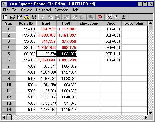
Select the co-ordinates of point 994006 and select Edit/Fix, clicking on it to remove the tick.
Now re-run the check. (Horizontal/Check)
Note the results (or print them out). The co-ordinates calculated for 994006 have moved about 11 centimetres, but the check still yields several errors, although they are more distributed than before.
Following our original line of enquiry we will now fix point 994006 again and this time allow point 994005 to float.
Select the co-ordinates of point 994006 and select the toggle menu Edit/Fix to fix this point again.
Select the co-ordinates of point 994005 and select the toggle menu Edit/Fix to allow this point to float.
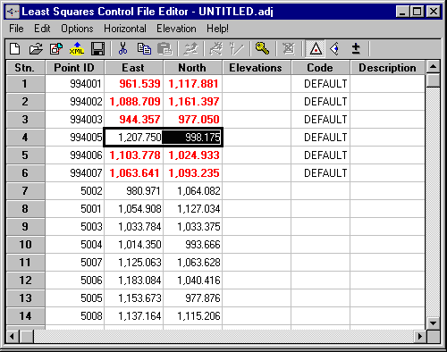
Now re-run the check. (Horizontal/Check)
Now the check shows us that there is no major observational errors and that point 994005 has moved by about 17cms.
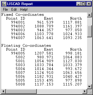
We verified the co-ordinates with the contractor and were informed, that a typing mistake was made.
The 994005 East co-ordinate should be: 1207.570.
Now edit the east value of point 994005 by double clicking on the edit field and entering 1207.570. Now fix the point 994005 once again.
- Run the Full Least Squares Adjustment
We can now continue by running the adjustment. Select Horizontal/Adjust/ASCII Output.
This process adjusts the network and calculates final co-ordinates for all but the known (red) stations.
Upon running the adjustment, a report is produced detailing the adjustments made. No excessive errors should be indicated anywhere.
Especially have a good look at the last section of the report, the "Error Analysis".
The indicated standard deviations at 95% confidence should not have outliers and be in line with the distances between the stations and the required quality of the survey.
Ideally the error ellipses should be near circular and the variance factor below 2.5.
Please refer to the Help system, chapter: "Least Squares Adjustment Theory" for an in-depth description of the underlying theory of the adjustment.
Upon closing the report a dialog will ask for permission to update the spreadsheet preliminary co-ordinates.
Select Yes.
- Update the Adjusted Points into the LISCAD Data Base
The final step consists of transferring the stations to the SEE database. Select Horizontal/Update Co-ords.
The Update Co-ordinates dialog highlights the stations that will be transferred to the database.
Normally the known stations already exist and so are not selected by default. In this case we corrected station 994005. Therefore click on station 994005 while holding the Control key pressed to select it as well.
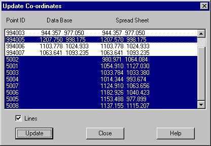
Check the Lines check box. This will transfer the observation lines used in the adjustment allowing you to see the layout of your network to see if it is structurally sound.
Press Update.
We can now close the spreadsheet window. The data on the stations and observations for this adjustment can be saved in file "Network.adj" for later retrieval and review.
Conclusion
You have now completed this tutorial and should have a good understanding of how to perform network adjustments using the least squares adjustment method.
You have also learnt how to:
- Extract network observations from the field file;
- Manually correct stations and observations;
- Examine the error and adjustment report for problems;
- Perform the network adjustment procedure;
- Save the calculated and updated station co-ordinates in the database;
- Save the information on the network, both stations and observations, in a special adjustment file.