To complete this tutorial you will require the Input/Output, Computations and Profiles & Design modules.
Aim
The aim of this tutorial is to import a DGN file and then perform recommended file maintenance procedures to facilitate improved file manipulation in the LISCAD Surveying & Engineering Environment.
Before you begin
Select this button to install the required data files.
- Install the Required Import Functionality
Select File/Open and open the file called "File Maintenance.SEE".
The first step is to import the MicroStation DGN file into LISCAD.
Select Task/Data Conversions/Import. If MicroStation is on the Import menu then select it. If it is not on the menu select Import / Add/Remove. This will open the Add / Remove Imports dialog.
Locate MicroStation in the Available list and click on it.
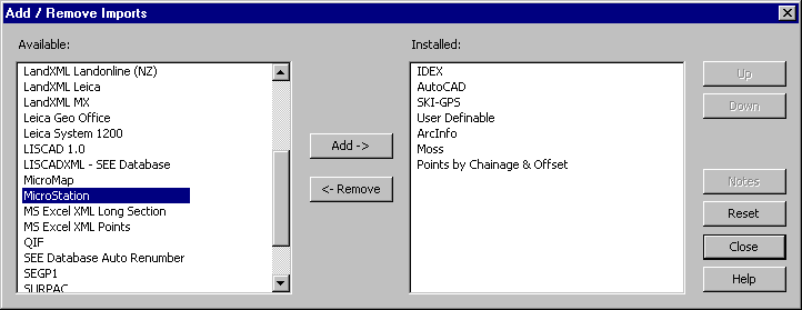
Press the Add-> key to move it into the installed list. (Alternatively you can double click on MicroStation in the Available list to move it into the Installed list.)
Click on MicroStation in the Installed list and use the Up and Down buttons to place it in the list in your required order.
Press Close.
Now go to Data Conversions/Import and the menu will include MicroStation in the menu at the position you selected.
- Import a MicroStation Data File
Select MicroStation to open the Import dialog.
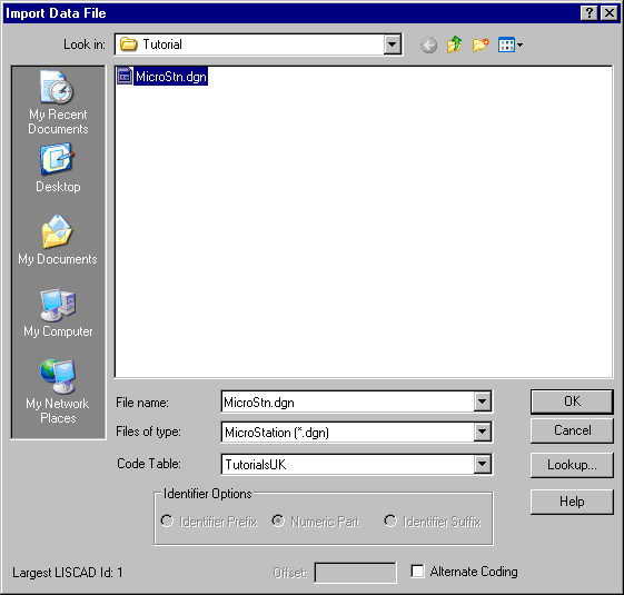
MicroStation cell names are treated as feature codes. Therefore the symbol associated with a feature code in the code table will be used if that feature code is matched to a cell name either directly or via a lookup table.
Note that if the Alternate Coding check box is not selected, the MicroStation Level number will be treated as the group name.
If the Alternate Coding check box is selected, the code of an element will be extracted from the MicroStation Design file as a reflection of the elements level number, colour, line weight, and line style. Each of these MicroStation numeric element attributes are zero filled in the resulting feature code. For example, in a MicroStation Design file, an element has a level number of 2, a colour of 4, a line weight of 6, and a line style of 7. The resulting feature code will be generated as 02004067 and this code will be used in the code/lookup table to associate attributes with the element.
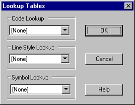
Press the Lookup button and make sure that all the lookups are set to [None] and press OK to return to the Import dialog.
Make sure that the Code Table is set to "Tutorials", then select the file "MicroStn.dgn" and press OK.
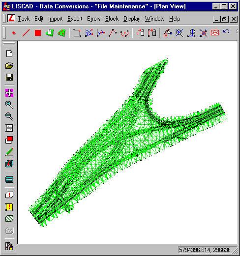
- Filter the Points
Select Utilities/Report/Statistics to produce a statistics report for the currently open data base.
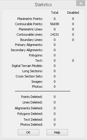
The Statistics dialog box displays the number of existing and deleted objects of different types. It also reports on the number of disabled objects in the data base.
Note that a line string which may consist of numerous line segments only counts as a single line object in this report.
A common problem when importing CAD drawing files such as DWG, DXF or DGN files is that points are duplicated at each common end point between objects. This results in a data set containing large amounts of redundant data and very little topology.
Therefore it is highly recommended that after importing these files it is always a good idea to filter and remove the excess data from the LISCAD project.
Select OK to exit the Statistics report dialog.
Select the Utilities/Maintenance/Filter Points command.
The Filter Points dialog permits the user to remove points from the database within specified tolerances.
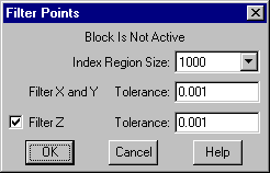
Select a Region Size of 1000.
This region size will be used in the filtering process to index the data into a number of regions. By selecting an appropriate region size the speed of the filtering process will be maximised. Typically, a region size between 500 and 1500 points will give the fastest results, but this will depend on the hardware being used and the amount of available memory.
In the Filter X & Y Tolerance field key in an East and North difference tolerance of "0.001". Points which are within the specified distance of each other in both the East and North directions will be filtered.
Select the Filter Z checkbox and key in an elevation difference tolerance of "0.001". This will ensure that only points that are within 0.001 in the x, y and z directions will be considered to be the same points and will be filtered out.
Select OK to perform the filtering operation.
The filtering operation may take a reasonable period of time to complete, particularly for large data sets, depending on your computer processor. This is because apart from filtering points out of the data set it is also making the correct topological associations between points and lines as well as indexing them into a relational geographic data base.
Note:
- During the filtering process, each point in the data base is compared to all other points and those within the tolerances specified are deleted.
- Lines associated with points deleted during the filtering process are automatically amended to the position of the appropriate point remaining in the data base.
- The attributes of a point remaining in the data base may be automatically amended during the filtering process to assume certain attributes of deleted points.
- The elevation of a deleted point will be transferred to the appropriate remaining point if the remaining point did not initially have an elevation.
- If a deleted point is contourable, then the appropriate remaining point also becomes contourable, even though it may initially have been non contourable.
Now Select Utilities/Report/Statistics which will produce a statistics report for the currently open data base.
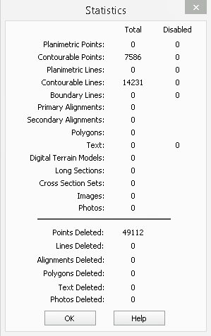
Notice that the statistics report is now showing that 49,112 points have been deleted from the LISCAD SEE project. All of these points were duplicates.
Select OK to exit the Statistics report dialog.
Next click on Block/All.
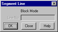
Select Task/Computations/Edit/Segment Line
- Filter the Lines
Segment Line breaks line strings into individual two point lines and arcs, containing points on the arc, into individual arc objects.
Select OK to segment the selected line(s) or arc(s).
Note: For straight lines the line will be broken at every point in the line, so for a line consisting of n points, n-1 lines will result. For arcs containing n points on the arc between the tangent points n+1 arcs will result.
Select Utilities/Report/Statistics again to see how many line objects are now in the data set.
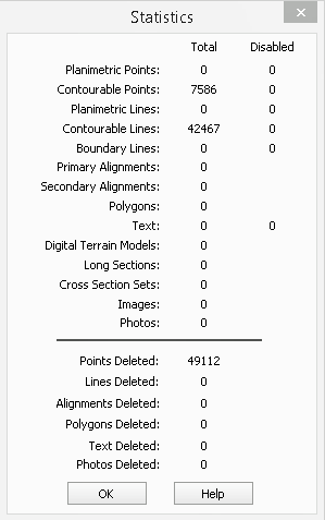
Notice that the statistics report is now showing that the project has approximately 3 times the number of line objects in the file as a result of segmenting the lines.
This clearly displays that the Segment Lines command has successfully broken line strings into individual two point lines.
Select OK to exit the Statistics report dialog.
Next we need to Filter Lines.
But first click on Block/All.
Select Task/Utilities/Maintenance/Filter Lines command.
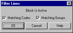
The Filter Lines dialog permits the user to remove from the data base lines which are wholly duplicated by other lines. This feature is particularly useful if duplicate lines have been collected or imported into the system. This function is Block sensitive and only filters line and spline objects.
Select Matching Codes and Matching Groups. This will only filter out lines that not only consist of the same points but also have the same codes and are on the same groups.
Select OK to perform the filtering operation.
Select Report/Statistics again to determine how many lines have now been deleted out of the data set.
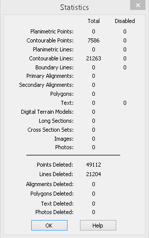
Notice that the Filter Lines command has deleted 21,204 duplicate lines.
Select OK to exit the Statistics report dialog.
Now select File/Close to close the LISCAD project altogether.
- Clean the Data Base
Next select the command Maintenance/Clean Data Base
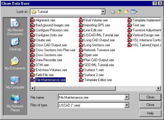
The Clean Database command removes deleted objects from the data base.
Note: This command is only available if there are no data bases currently open.
Select the folder in which the data base is located and accept the name of the existing data base to be cleaned - "File Maintenance.see".
Select the Clean button and then select Yes to permanently remove deleted objects.
Once the Clean command is used, previously deleted objects can no longer be undeleted.
- Check the Integrity of the LISCAD Data File
Now we wish to use the LISCAD Integrity Check command which checks for and resolves any anomalies in a data base.
Click on the Maintenance/Integrity Check command.
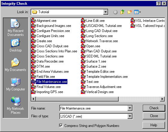
Select the folder in which the data base is located and accept the name of the existing data base to be checked - "File Maintenance.see".
Check the Compress String & Polygon No's option to compress any gaps in string and polygon numbers.
Note: These objects will only be renumbered if any deleted objects have been removed from the job using Clean Database previously.
Select the Check button to carry out the integrity check, resolve any anomalies and report the findings.
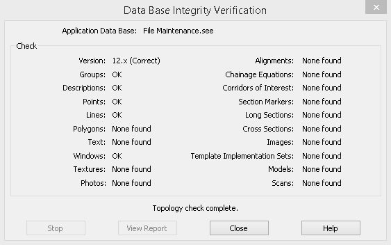
When an integrity check is carried out on a data base, a copy of the original file is created in the current data folder and given the file extension ".bak".
- Optimise the Data Base
Now select File/Open and open the file called "File Maintenance.see".
Select Maintenance/Optimise Data Base command.
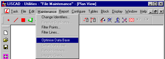
The Optimise Database command improves data base response times. Using this function can substantially improve the time taken to display the objects in the data base. This function will have the most noticeable effect on large data bases. Upon selecting this function the optimise process starts immediately and displays a completion message when the process is finished.
Select Report/Statistics to review the current status of the data base.
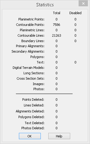
Notice that the Statistics report no longer reports on any Deleted Points or Lines. This is because the Clean command has permanently removed these deleted objects from the LISCAD database.
Select OK to exit the Statistics report dialog.
- Renumber the Point Identifiers
Now select Maintenance/Change Identifiers command which allows the point identifiers in the currently open data base to be changed.
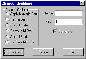
Select the Renumber radio button and enter 1 in the Start field. If the Range field is left empty the entire data base will be renumbered.
This nominates that you wish to renumber the numeric part of the identifiers of the entire file commencing at 1.
Note: The Compress option is always checked for this option.
By selecting Change with the Compress option active any gaps in the numbering system will be removed from the range.
Accept the Change button to alter the point identifiers according to the options selected.
Conclusion
You have now completed this tutorial and should have a good understanding of how to import a CAD file.
You have also learnt how to:
- Check the object statistics of the currently open LISCAD database
- Filter duplicate Points
- Segment lines and arcs
- Filter duplicate Lines
- Clean the LISCAD database of deleted objects
- Perform an integrity check and optimisation of the LISCAD database
- Renumber Point Identifiers