To complete this tutorial you will require the Modelling and Computations modules.
Note: This tutorial cannot be completed using LISCAD Lite.
Aim
The aim of this tutorial is to show you how to generate digital terrain models.
You will learn how to:
- Segment breaklines
- Validate and correct errors
- Form the terrain model
- Display contour labels
Typical Scenario
You have a project that you wish to form a digital terrain model of. The model may then be used to show contours, extract long or cross sections, or compute volumes.
Breakline segmentation is typically used prior to forming the model. It automatically adds additional points into curved breaklines, so that the model and resulting contours smoothly follow the splines and arcs. By placing these additional points on a unique group, they can be easily turned off once the modelling process is complete.
Before you begin
Select this button to obtain the required data file.
Now proceed with the steps below.
- Object Colour Representation
Select File/Open and open the file called "DTM.see" in the Tutorial folder.
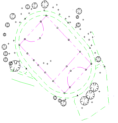
If Display / Features has "Use Colour Number" switched off and your system colour configuration is set to the default the colours displayed represent the following:
- Points in Black are DTM points and will be used in the model formation
- Points in Blue are Planimetric points and will not be used in the model formation
- Lines in Green are Breaklines and will define the edges of triangles
- Lines in Purple are Planimetric lines and will be ignored in the model formation
- Segment the Curved Breaklines
Select Task/Terrain Modelling and Edit/Breakline Segmentation.
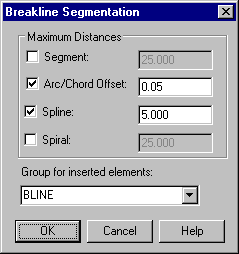
Set Arc/Chord Offset to 0.05.
Set Spline to 5.
Set Group for inserted elements to BLINE by typing BLINE into the dialog box
Select OK.
Any breakline arcs are segmented such that the arc to chord offset for any segment is not greater than 0.05 metres.
Any breakline splines are segmented such that spline points are no more than 5 metres apart.
The new points are placed on a new group called BLINE. - Validate the Data for Potential Model Errors
Select Modelling/Validation
Set Region size to 500.
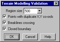
Select OK.
View or print the errors that relate to crossing breaklines.
- Correct the Modelling Errors
To find the validation errors select Task/Computations and then select Examine/Find/Errors.
The first error is attached to the rubber band.
Use Display/Window (or the Window tool) to view the relevant area.
Use Display/Features and the Point tab to turn on Identifiers. The problem is that 746 should be in both the lines and therefore needs to be inserted into the line between 148 and C1038.
Select Edit/Insert Point.
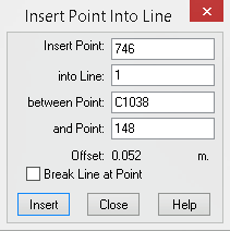
Snap and accept point 746
Snap and accept the line segment that runs from C1038 to 148.
Click Insert
Click Close
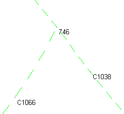
The data will now appear as shown here.
Select Examine/Find/Errors. Then click the Next button.
Use Display/Window (or the Window tool) to view the relevant area, getting very close in on point 120. You will then see that Point 120 and Point 9 are very close together and are in fact both observations to the same point. Use Examine / Bearing and Distance to verify that they are only 13mm apart.
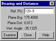
To fix this move Point 120 on to Point 9.
Select Edit/Move/Points, click in the Point(s) field and snap to point 120.
Do the same in the Ref Points field.
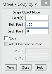
Click in the Dest. Point field and snap to point 9.
Select Move and the points will now be coincident.
Select Close
As these two points have slightly different elevations we will now filter the point data.
Select Display/Features/Points and turn Point Identifiers off.
Select the Fit tool to again see the whole project.
Go to Utilities/Maintenance/Filter Points. Set the X and Y tolerance to 0.001 and the Z tolerance to 0.01.
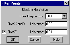
Press OK. This will remove point 120, but the line that was originally attached to point 120 is now attached to point 9.
Select Task/Terrain Modelling/Modelling/Validation
Select OK to validate the data that should now happen without errors. Select OK when validation is complete.
- Form and Display the Digital Terrain Model
Select Modelling/Form Model
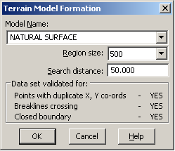
Set Region Size to 500 and Search Distance as 50. Keeping the search distance to a value that is a bit larger than the largest anticipated triangle side will prevent long thin triangles from being formed around the edges, without the need to create a boundary.
Enter Model description (Optional)
Select OK
When modelling is complete select OK to clear the Report dialog.
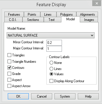
Select Display/Features/Model
Make the settings as shown below, then select OK to see the contours and labels as specified.
Tip: If the job you are modelling has a large number of points, this may cause the job to take a while to redraw. You can stop a job redrawing at any time by right clicking anywhere on the screen.
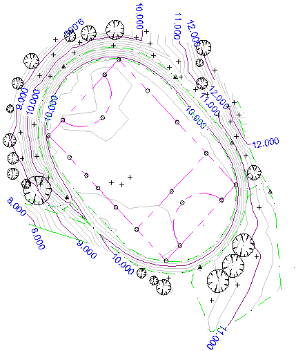
- Create Contour Label Lines
Additional contour labels can be placed in any position as required by the user.
Select Edit/Add Label Line
Using the left mouse button, place label lines as required.
When all lines are placed, select the Redraw tool.
To delete label lines select Edit / Delete Label Line
To move contour labels select Edit / Modify Label Line
Conclusion
You have now completed this tutorial and should have a good understanding of generating digital terrain models.
You have also learnt how to:
- Segment curved breaklines.
- Validate data prior to modelling
- Find and fix reported validation errors.
- Insert points into lines.
- Move points by co-ordinates.
- Create a digital terrain model
- Control the display of model features, contours and labels.
- Place, and edit additional contour label lines.