To complete this tutorial you will require the Profiles & Design module.
Note: This tutorial cannot be completed using LISCAD Lite.
Aim
The aim of this tutorial is to output a project to a CAD file from the Cross Section View.
Typical Scenario
A Cross Section project has been completed in SEE and we now want to output this data to a CAD file for final plan preparation. In this case we will create a LISCAD CAD file (*.lcd).
Before you begin
Select this button to install the required data files.
Now proceed with the steps below.
- Load the Cross Section CAD Output Parameter File
Select File/Open and open the file called "Cross CAD Output.see" in the Tutorial folder.
Select CAD Output! from the Profiles & Design Task in the Cross Section View.
The Cross Section CAD Output dialog appears.
This dialog defines the parameters by which the cross sections are to be output to either LISCAD CAD, AutoCAD DXF or MicroStation DGN formats. This dialog acts as a guide to the various CAD Output options.
In this tutorial we will be outputting to LISCAD CAD, hence select the button LISCAD CAD for Windows.
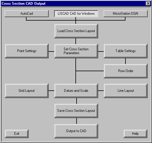
The Load Cross Section Layout button loads an existing cross section layout. Select "CrossTut" from the drop down list. Press Load to return to the Cross Section CAD Output dialog.

Note: If no CAD output layouts exist then default values are set.
- Set the Cross Section Output Parameters
Select Set Cross Section Parameters, select the Utilities cross sections and make the settings as shown below:
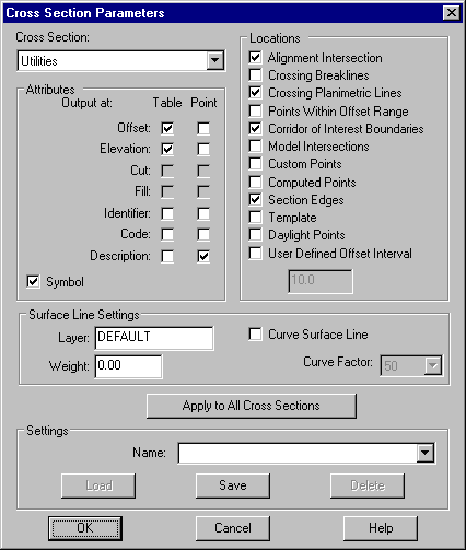
The Apply to all Cross Sections option applies the settings currently set to all cross sections in the drop down list.
Select "Natural Surface XS" from the Cross Sections list and make the same settings as for the Utilities cross sections, except for the Symbol check box. Press OK.
The dialog will close and the display settings will be applied to the "Centre Line" cross section.
- Set-up the Row Order and Names of the Tables
Now select the Row Order option, which controls the row order in the cross section table that is output to a CAD system.
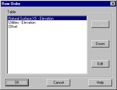
The Edit Button allows the user to Edit the name of the Row.
Highlight the Row name and use the Up & Down buttons to replicate the settings shown above.
Select OK to return to the Cross Section CAD Output Dialog.
- Set-up the Grid Layout
Select the Grid Layout button and make the settings shown below.
The Frame group controls the display of a frame around the outer limits of the cross section region.
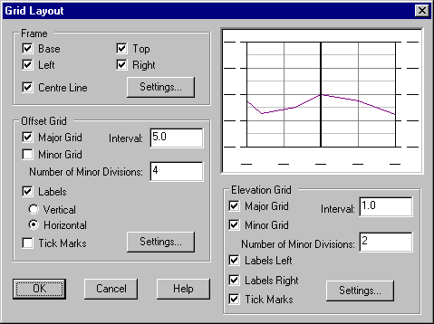
The Offset Grid group controls the display of the vertical line elements (offset) of the grid and the Elevation Grid group controls the display of the horizontal line elements (elevation) of the grid.
Select OK to return to the Cross Section Output Dialog.
- Set-up the Line Layout
Select the Line Layout button and make the settings shown below.
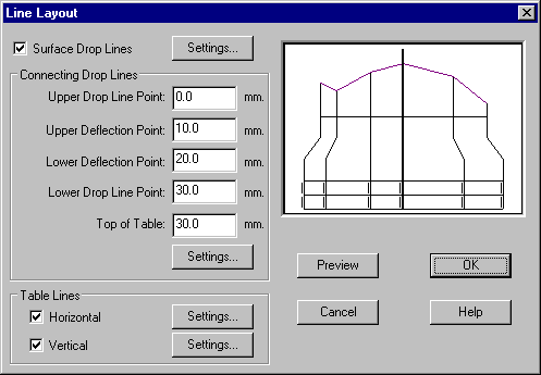
The Connecting Drop Lines group controls the size and position of the drop lines that are drawn between the base line of the grid and the top of the table.
These values are measured relative to the base line of the grid.
Whereas the Table Lines group controls the output of horizontal and vertical table lines to a CAD system.
Select the Preview button to apply the positional changes made to the display area on the dialog.
Select OK to save the settings and return to the Cross Section CAD Output Dialog.
- Set-up the Datum and Scale for the Cross Sections
Select the Datum & Scale button.
This dialog controls the scale and the dimensions of the cross sections to be output to a CAD system.
Please make the settings shown below.
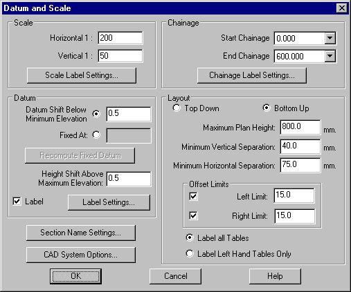
The Scale group is used to set the scale that is used when plotting the drawing from the CAD system.
For all CAD systems, the file is created according to the coordinates set in the data base.
The scale entered here is used to calculate the text and symbol sizes in ground units, such that when plotted at the entered scale, they will be at the required size on the plan.
The Layout section determines the layout of the cross sections that are output.
For each chainage range the cross sections will be output in columns of increasing chainage from left to right.
Select OK to save the settings and return to the Cross Section CAD Output Dialog.
- Save the Cross Section CAD Output Parameter File
Select Save Cross Section Layout.
Key in or select from the Layout name drop down list the Cross Section Layout File that the current settings are to be saved to i.e. "CrossTut".

The name of the file that is saved will be in the format LAYOUT name.XPF (i.e. CrossTut.xpf) and will be stored in the defined User Folder.
This Cross Section Layout file can be recalled on subsequent jobs via the Load Cross Section Layout dialog.
- Create the Cross Section CAD File
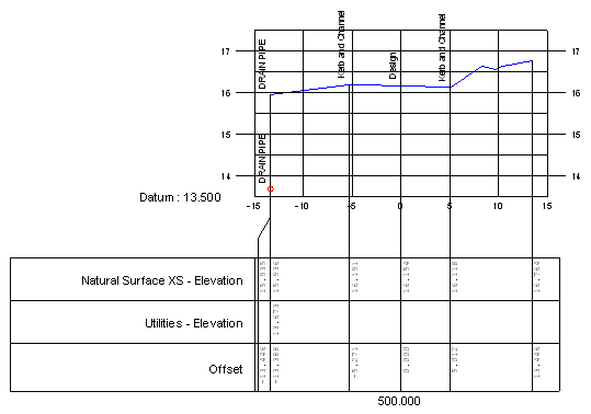
From the Cross Section CAD Output Dialog select the Output to CAD button and create a LISCAD CAD for Windows (*.lcd) file, called "Cross CAD Output.lcd". If Open CAD File is checked the file will be opened automatically after creation, in the application that the CAD file extension has been associated with, in this case LISCAD CAD.
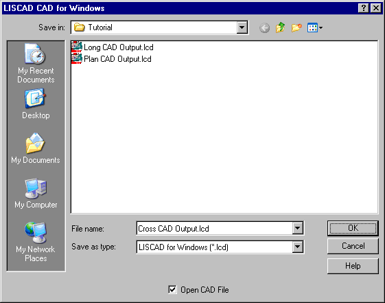
If you do not wish to open the file directly you can open this file later by running LISCAD CAD, then go to File & Open the file (*.lcd) Data/Tutorial/Cross CAD Output.lcd.
Conclusion
You have now completed this tutorial and should have a good understanding of how to output a Cross Section to a CAD file.
You have also learnt how to:
- Load a new Cross Section Layout
- Set Cross Section parameters - Point, Table & Row Order
- Set the Datum & Scale of the output to CAD
- Save a Cross Section Layout
- Open a Cross Section CAD file in LISCAD CAD