To complete this tutorial you will require the Computations module.
Aim
The aim of this tutorial is to create a new SEE project based on a flat plane, utilising a combined scale factor to control the relationship between ground distance and grid distance on the plane.
You will also be exposed to:
- Creating points by co-ordinates.
- Controlling what features are displayed.
- Controlling the distance configuration.
- Examining bearing and distance between points.
Typical Scenario
A typical scenario for using a plane project with a combined scale factor would be:
"The region covered by the survey is fairly flat, hence a single combined scale factor for the whole survey is appropriate. There are two control points with known co-ordinates that are the datum for the survey, but they are not on a known projection. The computed grid distance between these points is shorter than the measured ground distance (corrected for slope) by a factor of 0.99990001. Hence all ground distances are to be corrected by this factor to ensure that computed co-ordinates are on the same datum as the control."
- Open the New File Dialog Box
Run SEE and select File/New to display the New File dialog.

Use the Save In field to navigate to the Data folder.
Click in the File name field and type "Plane Tutorial"
Ensure that the Projection Type: field is "Plane". This ensures that all calculations will be based on a flat grid and not on a projection.
- Set-up the Earth Constants
Select the Earth Constants button and ensure the dialog fields are as shown below.
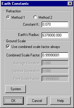
Ensure that the Use Combined Scale Factor check box is ticked, and set the Combined Scale Factor to 0.99990001.
Any ground distances entered in this project will be automatically multiplied by this factor to obtain grid distance or calculate co-ordinates.
Select OK to return to the New File dialog.
- Enter the Project Details and Create the Project.
Click the Details button, enter any details you wish in the available fields, then press OK to return to the New File dialog.
Click OK to create the new project. The new project is now automatically opened.
- Create Two Points by Entering Co-ordinates
Select Task/Computations
Then select Create/Point followed by Method/Co-ordinates.
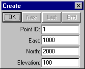
Complete the fields as shown above left and select OK to create point 1.
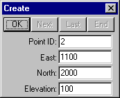
Complete the fields as shown above right and select OK to create point 2.
Then close the Create dialog.
- Set-up the Point Display
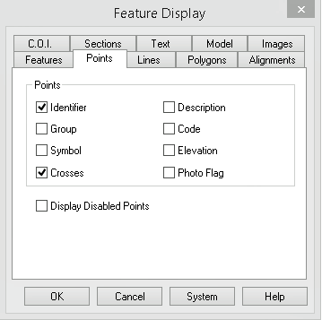
Select the Display/Features command and then the Points tab.
Check Identifier and Crosses.
Then select OK to close the dialog and see the point identifiers and crosses.
Tip: You can quickly show the Display Features dialog by right clicking anywhere on the screen and selecting it from the floating menu.
- Examine the Plane Distance Between the Two Points
Select the Examine/Bearing & Distance command.
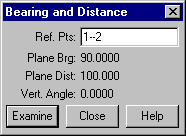
With the focus on the Ref. Pts: field, snap and accept point 1, then snap and accept point 2 to display the results.
Note that the plane (i.e. grid) distance is 100.000.
- Examine the Ground Distance Between the Two Points.
Select Task/Utilities.
Select the Configure/Units command.
Select Distances/Ground instead of Distances/Grid.
Select OK to close the dialog and change the distance units to Ground.
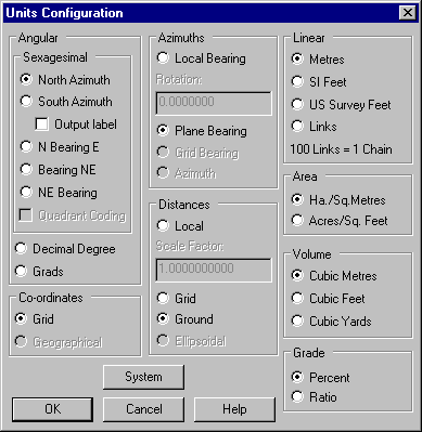
Select Task/Computations.
Then select the Examine/Bearing & Distance command.
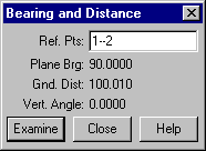
With the focus on the Ref. Pts: field, snap and accept point 1, then snap and accept point 2 to display the results. Note the ground distance is 100.010.
Note also that the ratio of grid to ground distance in this practical example calculates to be 0.99990001, which was the combined scale factor set when the project was created.
Conclusion
You have now completed this tutorial and should have a good understanding of how to create a plane project, and utilise a combined scale factor to control the relationship between grid (plane) and ground distances.
You have also learnt how to:
- Create points by co-ordinates.
- Control what features are displayed.
- Toggle the system between configuration for grid and ground distances.
- Examine bearing and distance between points.