To complete this tutorial you will require the Computations module.
Note: This tutorial can only be partially completed using LISCAD Lite.
Aim
The aim of this tutorial is to show you how to create new objects using the Computations task. In particular, you will learn how to:
- Create a point by co-ordinates
- Generate a line by traverse input
- Create Arcs by Tangent and IP's
Typical Scenario
An engineering plan has been provided to you showing a design centreline. This information is to be input into the project.
Before you begin
Select this button to obtain the required data file.
Now proceed with the steps below.
- Open the Example File and Turn Off the Display of Contours
Select File/Open and open the file called "Create.see" in the Tutorial folder. This file contains natural surface data that has been processed from various sources and modelled.
- Set-up the Codes Prior to Creating any Points and Lines
Use the code lists as shown below to select "CL" for the current point code (left in picture) and the current line code (right in picture).

- Create a Starting Point by Entering Co-ordinates
Select Task/Computations
Select Create. If the Line Segment menu item is ticked, select it to turn it OFF, otherwise leave it un ticked. This ensures that multi-segment lines will NOT be divided into separate line objects.
Select Create/Point and then Method/Co-ordinates.
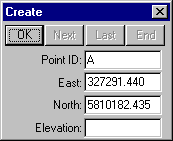
Complete the fields as shown and select OK to create point "A".
This is the start of the design centre line.
- Create a Line by Entering Traverse Directions and Distances
Select Create/Line and then Method/Traversing.
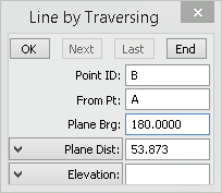
Complete the fields as shown and select OK to create point "B".
You will now see the line from A to B and a rubber band will be attached to point B.
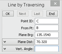
Complete the fields as shown and select OK to create point "C".
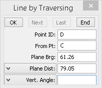
Complete the fields as shown and select OK to create point "D".
Then select End to conclude the line creation.
- Display Only the Groups you are Currently Interested in.
Select Display/Groups.
Select None.
Then select C/L and ROAD while holding down the Ctrl key.
Only those groups should now be highlighted.
Select OK and only objects on the selected groups will be displayed.
Tip: You can quickly show the Display Groups dialog by right clicking anywhere on the screen and selecting it from the floating menu.
- Display the Attributes of the Lines.
Select Display/Features and then the Lines tab.
Turn on Bearing and Distance and select OK.
You now see the bearing and distance attributes of the line segments on the screen.
- Create Arcs by Tangent Lines and Intersection Points
Select Create/Arc
Select Method/Tangents & IP
Under Tangent Line 1, snap and accept the line between A to B.
Note: Depending where you snap on the line segment the Reference Points may say A--B or B--A. Either case is acceptable as direction is not important in this context.
Under Tangent Line 2, snap and accept the line between B to C.
Under Radius, enter 75.0
Select Fillet Lines.
Select Compute and the proposed new arc is drawn.
Select Accept to create the arc.
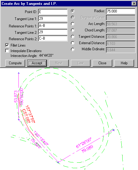
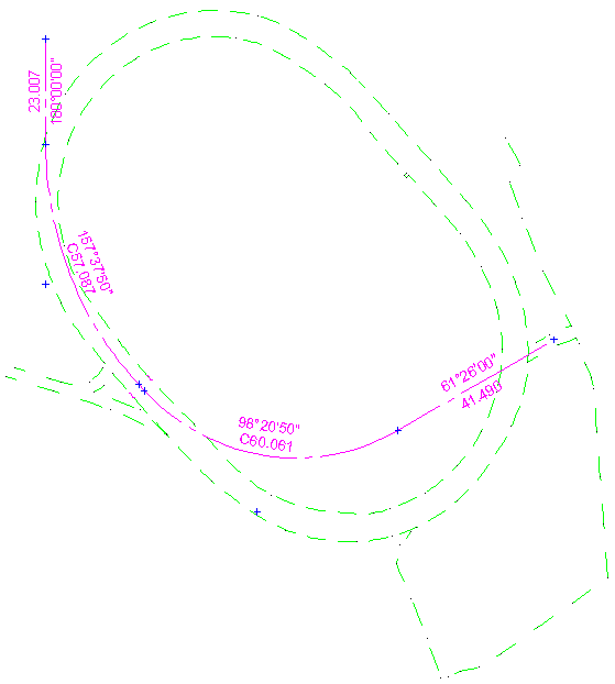
Using a similar process, create an arc for the tangent lines intersecting at C using radius 50.
Then close the dialog.
The design centre line that you created should look like this.
Conclusion
You have now completed this tutorial and should have a good understanding of creating objects in the Computations task.
You have also learnt how to:
- Control model display.
- Control whether lines are created as individual line objects or continuous line strings.
- Select appropriate point and line codes before creating objects.
- Create points by co-ordinates.
- Create lines by traverse entry.
- Control the display by groups.
- Create arcs from tangents and automatically fillet tangent lines.