To complete this tutorial you will require the Input/Output module.
Aim
The aim of this tutorial is to output a project to a CAD file.
Typical Scenario
A project has been completed in SEE and we now want to output this data to a CAD file for final plan preparation. In this case we will create a LISCAD CAD file (*.lcd).
Before you begin
Select this button to install the required data files.
Now proceed with the steps below.
- Loading and Editing the CAD Output Parameter File
Select File/Open and open the file called "Plan CAD Output.see" in the Tutorial folder.
You will first need to open a CAD parameter file in which all parameter settings made for the output to CAD are stored. To do this select Task/CAD Output.
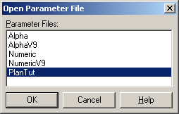
Select Settings/Parameter File/Open, highlight "PlanTut" and press OK.
The CAD parameter file (PlanTut.cpf) used has been previously created and set up using the CAD Output/Settings options to suit the particular type of project and the drawing required. The CAD parameter file settings govern the data and attributes passed to the CAD file. After you complete this tutorial view and experiment with the various settings to understand their relationship with the created CAD file contents. Carefully setting up one or more CAD parameter files to suit various types of projects will ensure that the created CAD file requires only a minimum of editing to produce the final plan.
Important Note: The CAD parameter settings for all 3 CAD Systems i.e. LISCAD CAD, AutoCAD DXF and MicroStation are held in a CAD parameter file and need to be set for each CAD system that is output to.
This tutorial provides an overview of what can be set in the CAD Output parameter file. Select the Settings command to view the settings that are available and then close the dialogs.
Select Settings/Codes.
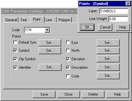
This opens the CAD Parameter Settings dialog. It is here that CAD parameters are set for codes.
In the example below any symbols that have the code "STN" will be output onto the LISCAD CAD layer "SYMBOLS" with a Line Weight of 0.00.
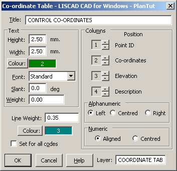
Select Settings/Tables/Co-ordinate...
This command opens the Co-ordinate Table dialog that is used to set the CAD output parameters for a co-ordinate table.
Note: CAD parameters can also be set for Radiation, Arc and Short Line tables.
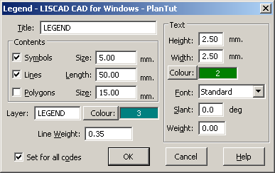
Select Settings/Legend
This command opens the Legend dialog that is used to set the CAD output parameters for a legend that contains one occurrence of every type of symbol, line style and polygon hatching that may be output to the CAD file.
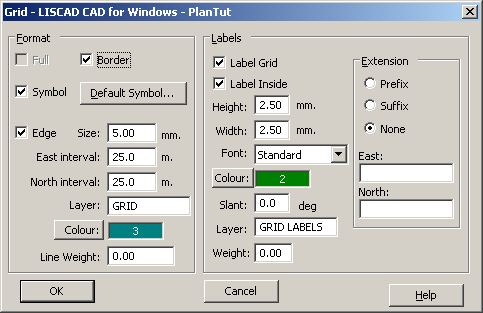
Select Settings/Grid
This command opens the Grid dialog that is used to set the CAD output parameters for a grid that may be output to a CAD file.
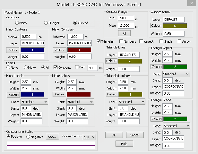
Select Settings/Model
This command opens the Model dialog that is used to set the CAD output parameters for a model that may be output to a CAD file.
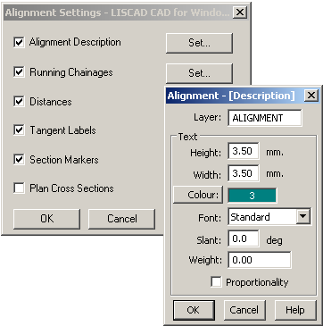
Select Settings/Alignment
This command opens the Alignment Settings dialog that is used to set the CAD output parameters for alignment objects that may be output to a CAD file.
- Create the CAD File
Select Output.
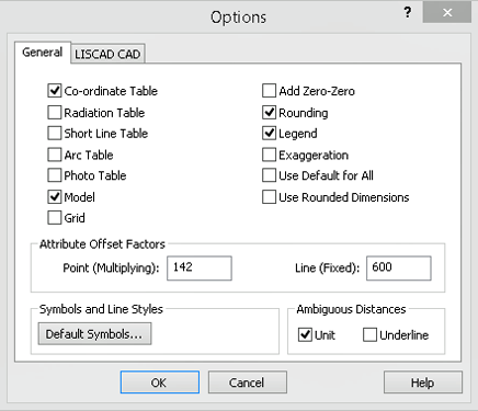
In the LISCAD CAD for Windows dialog select Options..., set the options as shown below and press OK.
In the LISCAD CAD for Windows dialog enter the File name as "Plan CAD Output.lcd" and set the Format settings as shown below.
If you have LISCAD CAD for Windows installed you can check the box labelled Open CAD File. This will automatically open the CAD application and open the file after it is created.
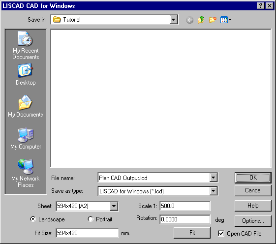
Press OK.
The file "Plan CAD Output.lcd" has now been created in the Tutorial folder.
If you have the Open CAD File check box ticked and you have the LISCAD CAD application installed the resultant CAD file will be opened automatically in the CAD application.
Conclusion
You have now completed this tutorial and should have a good understanding of how to output a project to a CAD file.
You have also learnt how to:
- Open a CAD parameter file (cpf).
- Set parameters for Codes.
- Set parameters for various tables.
- Set parameters for a legend, grid, model, and alignment objects.
You may later want to take "Plan CAD Output.lcd" and compare it with "Cadtut.lcd" that is installed with the LISCAD CAD for Windows tutorial.