To complete this tutorial you will require the Computations module.
Note: This tutorial cannot be completed using LISCAD Lite.
Aim
The aim of this tutorial is to show you how to convert a number of geometric objects, such as lines and arcs, into an alignment. You will learn how to:
- Set Alignment Attributes
- Generate an Alignment object
Typical Scenario
An engineering plan has been provided showing centreline design information. This information has already been input into the project. Now it is appropriate to create an alignment along the centre line, so that chainage can be computed.
Before you begin
Select this button to obtain the required data file.
Now proceed with the steps below.
- Set up the Display and Alignment Configuration
Select File/Open and open the file called "Alignment.see" in the Tutorial folder. This file contains a trial centreline that is to be turned into an alignment.
Select Display/Features and then the Lines tab.
Turn OFF Bearings and Distances, then select OK.
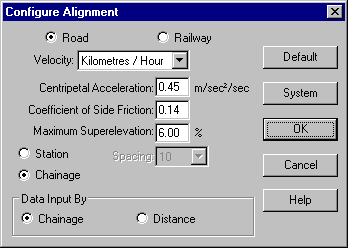
Select Task/Utilities and then select Configure/Alignment
Make the settings as shown below, and select OK.

- Set the Alignment Attributes
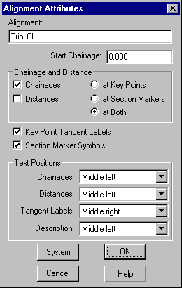
Select Task/Computations and then select Attributes/Alignment

Make the settings as shown and select OK.
- Create an Alignment by Tracing Lines
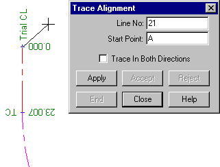
Select Create/Alignment, then select Method/Trace.
Click in the Line No: field, then snap and accept the start of the centreline as shown.
The alignment is created and you will see the chainages and tangent labels drawn.
Close the dialog.
Tip: If the job you are working with has a large number of points, this may cause the job to take a while to redraw. You can stop a job redrawing at any time by right clicking anywhere on the screen.

Conclusion
You have now completed this tutorial and should have a good understanding of how to create an alignment object.