To complete this tutorial you will require the Computations module.
Aim
The aim of this tutorial is to show you how to configure the precision and rounding for displaying dimensions to user required accuracy. You will learn how to:
Set precision and rounding values for co-ordinates, angles, distances, areas and volumes.
Change the display of rounding for various elements of the project.
Typically, you will only need to configure the precision and rounding settings once to cater for your particular needs. You should do this (to meet your particular needs) after completing the tutorial.
Also, it should not generally be necessary to edit the rounding attributes as we do in this tutorial, provided you have appropriate rounding attributes set for each code you use. Proper setting up of codes and their attributes in a code table, and use of appropriate codes for different types of objects will ensure that the precision and rounding is always what you desire without the need to edit.
Typical Scenario
It is a requirement that your plan must show dimensions to particular statutory precisions or rounded values.
Before you begin
Select this button to obtain the required data files.
Now proceed with the steps below.
- Open the Example Data File
From the Utilities Task select File/Open and open the file called "Configure Precision.see" in the Tutorial folder.
Select Display/Features, then the Features tab and check the Apply Rounding box. This will ensure that all rounding is displayed.
Use the display commands to zoom into the allotment shown below.
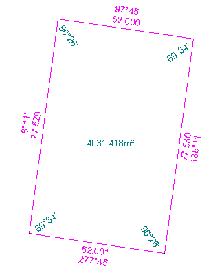
During this tutorial you may need to pan and zoom in closer than this image depicts so you can clearly see the changes that are made to the various dimensions. It is probably a good idea at this point to make yourself familiar with the various Display menu commands that are available.
- Set the Co-ordinate Rounding
Select Configure/Co-ordinates and set the values as shown taking note of the values for:
- XY Precision
- Z Precision
- XY Rounding 1
- Z Rounding 1
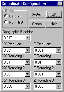
Press OK.
Select Display/Features then the Points tab and check the Elevation and Identifier boxes. Press OK.
Select Task/Computations then Attributes/Point.
In the Point Attributes dialog change the XY: and Z: Rounding field to show a value of 1 and press OK.
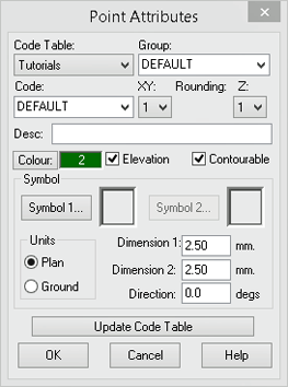
Note: A rounding attribute of 0 uses the Configuration values set for the Precision, whereas a rounding attribute of 1, 2 or 3 uses the corresponding Configuration values set for rounding.
Select Edit/Attributes/Point, make the following settings.
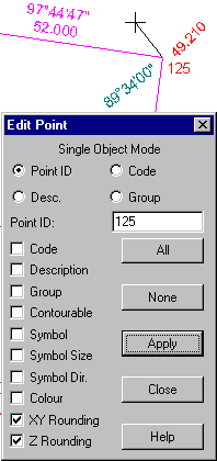
Click on point 125, which defines the top right-hand corner of the allotment and press Apply. The XY and Z Rounding values have now been set for point 125.
To check that you have set the co-ordinate rounding correctly for point 125 select Examine/Attributes/Point and click on point 125. You will see that XY Rounding and Z Rounding equals 1, as set in step 5.
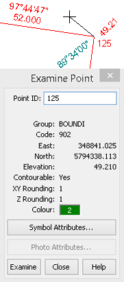
You will also notice that the elevation changed to 2 decimal places therefore indicating the rounding was correctly applied.
Press Close and edit the attributes in the same way for points 113, 114 and 126 that define the other 3 corners of the allotment.
- Set the Angle / Direction Rounding
You will now set and display the rounding for angles.
Note: The same settings for angle rounding apply to both line bearings and polygon angles.
In this example we will set the rounding for the allotment bearings. To do this first select Task/Utilities then Configure/Angles.
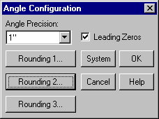
In the Configure Angle dialog make the settings as shown below and then press Rounding 2.
In the Rounding #2 dialog make settings as shown.
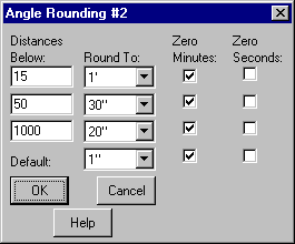
Press OK to close this dialog and press OK again to close the Angle Configuration dialog.
The following explains what the above rounding settings are. This will give you a better understanding of the results when we apply these rounding values.
Distances Below are distance ranges for which the corresponding rounding settings are to be applied.
Round To is the rounding used for the corresponding distance range. The default rounding entered will be used for any ranges not specified and also for polygon angles.
Zero Minutes is set for rounded bearings which are a whole number of degrees and should have the minutes displayed. For example 25° would display as 25° 00'.
Zero Seconds is set for rounded bearings which are a whole number of minutes and should have the seconds displayed. For example 25° 15' would display as 25° 15' 00".
Select Task/Computations then Attributes/Line.
In the Line Attributes dialog change the Bearing Rounding: field to show a value of 2, Bearing and Distance are ticked active and press OK.
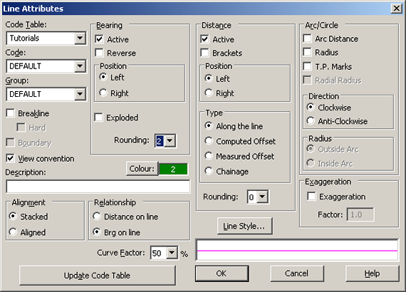
Select Edit/Attributes/Line, make the settings shown below.
Click on line 1 that defines the boundary of the allotment. All 4 sides of the allotment will be highlighted and Line No 1 will appear in the dialog
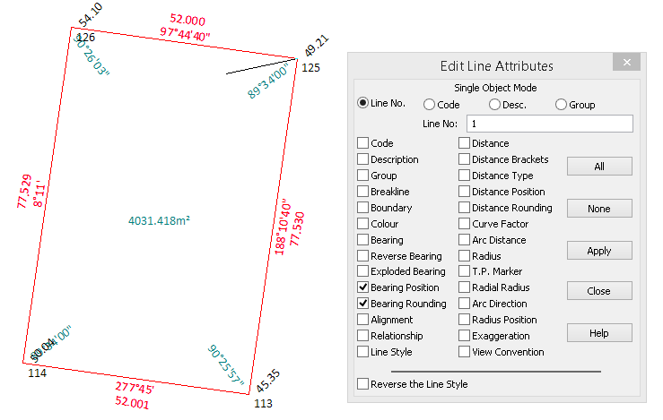
Press Apply.
The Bearing Rounding values have now been set for line 71 and the changes are shown below. This image shows the point identifiers and point elevations turned off. This has only been done for clarity and does not need to be done as part of the tutorial.
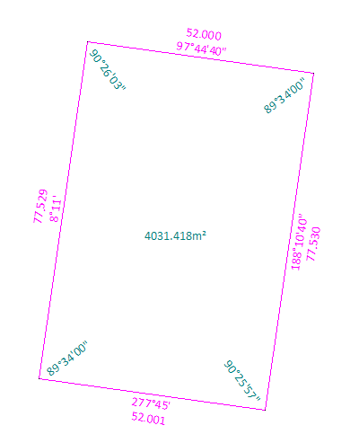
As a further exercise apply angle rounding to the polygon angles of the allotment.
Hint: You will need to set the polygon attributes for angle rounding.
- Setting Other Rounding Values
The rounding for distances, areas and volumes are set in the same way that we have set the angle rounding. You should take some time and familiarise yourself with these other rounding types.
As a final exercise select Display/Features then the Features tab.
Turn off the Apply Rounding option and press OK. The rounding that has been set in this tutorial has been turned off.
You should now use the appropriate Configure commands to set precision and rounding to suit your particular needs. Press the System button in each dialog to save the settings and have them automatically used for any new project.
Also ensure you set up a code table to match your needs and make sure each code has appropriate rounding attributes set.
This will minimise the need to edit data as it will be created with the required attributes to start with.
Conclusion
You have now completed this tutorial and should have a good understanding of precision and rounding in LISCAD.
You have learnt how to:
- Configure the precision and rounding settings.
- Apply the appropriate precision and rounding to objects via the objects rounding attributes.
- Toggle rounding display on or off.