To complete this tutorial you will require the Input/Output module.
Note: This tutorial cannot be completed using LISCAD Lite.
Aim
The aim of this tutorial is to learn how to setup and compute a Network Traverse.
Before you begin
Select this button to install the required data files.
- Install the Required Projection
For this tutorial we need to create a new project on the New Zealand Geodetic Datum 1949 for Mount Eden (NZGD49 Mount Eden). Before creating the project we will make sure that we have the NZGD49 Mount Eden projection installed.
Select Configure / Projections / Install/Remove Projections from the Utilities Task.
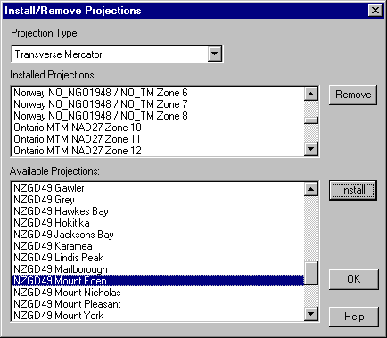
From the Projection Type dropdown list select Transverse Mercator. Now look in the Installed Projections list to see if the NZGD49 Mount Eden projection is already installed.
If it is not installed, locate it in the Available Projections list click on it and press the Install button.
While you are here it would be a good idea to remove any currently installed projections that you are not likely to use and install those that you will be using in the everyday course of your work. By doing this it will be quicker and easier to find the projections you want when creating new projects. Just select the projections you don't normally want to use from the Installed Projections list and press the Remove button.
You are not deleting any projections only removing them from the list. You can always install them at a later stage should you find you need them.
Press OK to accept your selections.
- Create a New Project on a Projection
Now we can create a new project. Select File/New and enter a job name such as "Network Traverse.see".
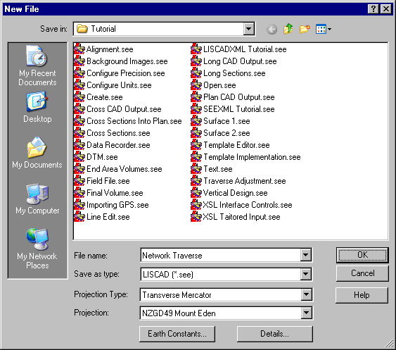
Select OK in the New File dialog to create a new SEE job.
- Select the Required Code Table
Before we proceed we will associate the required code table with this new SEE job. Select Tables/Code Table/Open.
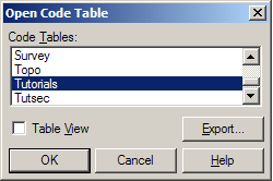
Select "Tutorials" and press OK. This will associate the code table with the current job and open up the code table in the spread sheet editor. Close the code table editor.
- Open and Configure the Traverse Spreadsheet Editor
Select Task/Field Transfer/Resolve/Traverses to bring up the Traverse spreadsheet editor.
Under View, Turn OFF Angles, Arcs and Elevations. In the menu, these columns are turned off when there is no "tick" beside them. These columns will no longer be visible in the editor.
Change Columns to desired Width.
Select File/Layout to save the Spreadsheet Column Settings as the System Defaults.
- Open the Traverse File
The Traverse Entry spreadsheet is very powerful allowing you extract data from field files, as well as adjust horizontal and vertical observations.
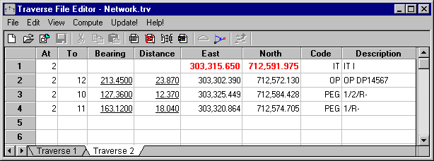
Select File/Open and open the installed Network.trv from the list. Press Open. Alternatively this information can by manually typed in by entering point identifiers (At and To) along with bearings, distances and start coordinates. Codes entered should match codes from the codetable, as when the traverse data is saved to the database, LISCAD uses these codes to draw the appropriate symbols and lines between the points.
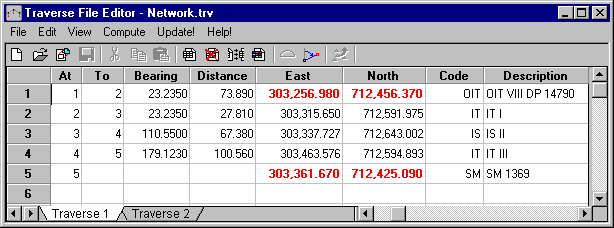
In the traverse file opened, you will notice that there are two traverses, to view the second traverse click on the tab at the bottom of the editor. To actually create a new traverse on a new sheet, the method would be Edit/New Traverse.
"Traverse 2" is an example of a radiation block. Radiation blocks are shown Underlined in the traverse data. Radiations can be set by either using the toolbar button or View/Set Radiation. Radiations can be entered within Traverses.
During reporting (using the Type 1 Traverse Sheet report) the traverses are output first, followed by the radiations underneath.
- Compute the Traverse
To compute the Traverse and write the points out to the database, the following procedure should be followed:
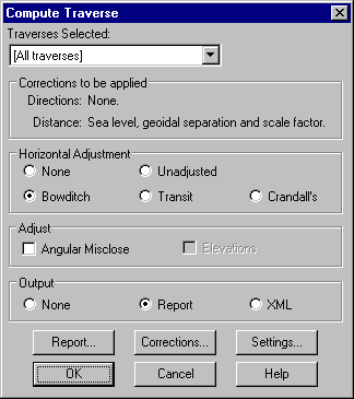
From the Traverse File Editor menu select Compute/Traverse.
Select the Traverse to be computed from the drop down list (usually All Traverses).
Select the Horizontal Adjustment Method (usually Bowditch in NZ).
Press the Settings button to set the accuracy and misclose warning limits. You can also set the scale you want to eventually plot the traverse at, and this is used by the system to place the graphic bearing and distance observations at a suitable offset from the traverse line.
Press the Corrections button to select the corrections to be applied to your observations. If you select "Ground Distances" check the Earth Constants and set the Average Elevation of the traverse which is needed to compute the Mean Sea Level correction for your distances.
Press the Report button to choose a Format. Custom is selected to produce your own customised traverse report or Type 1 if you want to produce a Traverse sheet suitable for lodgement with LINZ.
In the main dialog, select OK to calculate the traverse and produce the report.
After generating and saving/printing the traverse report, the points and lines will want to be saved to the database.
- Save the Adjusted Co-ordinates to the SEE Data Base
From the Traverse File Editor menu select Update!
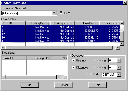
If you want LISCAD to draw lines between your traverse marks, check the Lines check box.
In the Observed Box, check Bearings and Distances, if you want LISCAD to annotate your lines with the observed bearings and distances as entered in the Traverse Entry.
Select the points you want to update into the SEE data base. The list shows the points and the new co-ordinates of the points. If the points already exist in the database, the existing co-ordinates will also be shown (not applicable in this tutorial as we are using a new project that does not have any existing points). The points are selected using the standard Windows selection methods. Click on the Top point and hold down Shift and click on the bottom point. This will cause all points/text to be highlighted. Alternatively, use CTRL to select / unselect individual points.
Select OK to Update the Points into the database.
Close the Traverse Editor.
- View the Results
Use Display/Fit to view the entire database.
Your Points, Symbols, Lines, Descriptions and "Observed" bearings and distances will now appear in SEE, (provided that the codes you used are in the Code Table). SEE should look something like below:
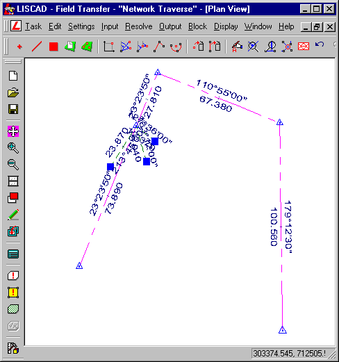
In the example above, Display/Features has been used to turn Point Descriptions and Symbols on. Also the bearing and distances shown are text objects and therefore have been moved to be seen more clearly. The symbols are drawn based on the attribute settings in the Code Table.
In SEE, you can then create other points and lines in Computations, Move or Delete Text etc. Refer to the main tutorials and online help with your LISCAD installation for help in doing this.
When the plan is basically correct, you can export the plan out to LISCAD CAD or any other CAD system, such as AutoCAD or MicroStation, you are using.
It is most important that the CAD Parameter File(s) are set up correctly for each of the codes used in SEE. This ensures that things such as mark descriptions, symbol sizes, line-weights, text fonts, text sizes etc. are all exported as you expect them. The CPF files control this output. In most instances you will have a number of different types of CPF to output different types of plan. For example, you will require different information output for a cadastral survey as opposed to a topographical survey. See other tutorials and the online help for more detailed information.
Conclusion
- You have now completed this tutorial and should have a good understanding of how to define and compute Network traverses.