To complete this tutorial you will require the Volumes, Modelling and Computations modules.
Note: This tutorial cannot be completed using LISCAD Lite.
Aim
The aim of this tutorial is to calculate the volume between a natural surface and a design surface (Two Surfaces) and output grid points for field set-out.
Typical Scenario
A surveyor has been contracted to determine the excavation quantities to fulfil the design of a development on a disused quarry site. The project design has been supplied and the surveyor has completed a survey of the existing surface of the construction site.
Before you begin
Select this button to obtain the required data files.
This project involves two data sets (From & To Surfaces) from which a third data set of height differences and no cut / no fill lines will be generated. The tutorial will also cover how to construct a grid over the output surface, interpolate heights onto the grid points and output the data for field set out.
The height difference data set forms a new database and consists of every point and line in the common area of the From and To models, as well as the points and lines computed at the intersection of the models and the common boundary. The computed elevation of each point in the new database is the height difference between the From and To models at that point.
The "From" surface, which is the natural surface, is in a file called "Surface 1.see".
Note: The "From" model is considered to be the original surface which will be (or has been) cut and/or filled to achieve the "To" surface.
- Compute a Volume Between Two Surfaces and Create a Height
Difference Data Set
Select File/Open and open the file called "Surface 1.see" in the Tutorial folder.
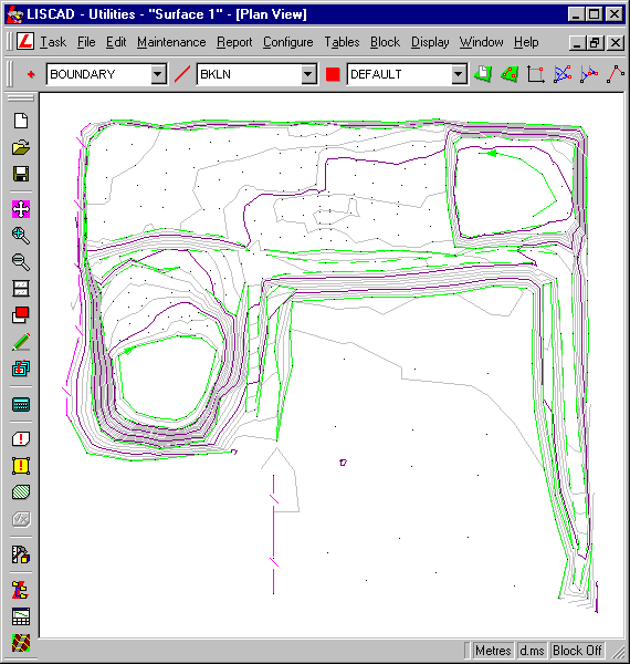
Click on Utilities / Configure / Point Identifier.
Set the Starting ID to 1, Construction Starting ID to C1000, with a Code of CONST. Click Unique Point Identifiers ON.
Save System settings and Close.
Select Task / Volumes / Volumes / Surface to Surface
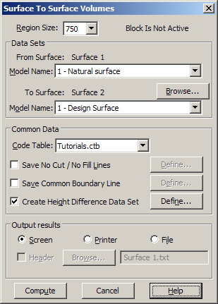
Check that the "From" Surface is "Surface 1" and "Model No =1 Natural surface."
At the "To" Surface select the Browse button to open the dialog box to select the 'To' database to be used in the comparison.
This may be the currently open database or any other database. Scroll down the File List and select the file "Surface 2.see".
Next check that "Model No= 1 Design surface".
Note: The 'To' model is considered to be the finished surface after cut and/or fill has been (or will be) applied to the 'From' surface.
Click on the Code Table Down Arrow and select "Tutorials". This is the code table to be used for setting the attributes of the common data.
To create a new data set with the height differences between the two models:
Select the check box "Create Height Difference Data Set"
Click on Define.
This allows the user to name the new Height Difference database, and assign feature codes to the points and lines included in this database
Type in File name for the Volume output file, "Final Volume".
Next select the Details & Codes button. It is here that database details and codes are set for any additional points and lines that are created when the height difference database is created.
Click on Point and Line Codes Down Arrows and set required Codes as shown below.
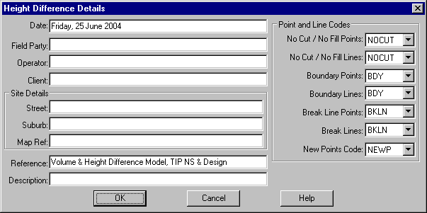
Type in any User Information as required.
Click on OK to return to the Create Height Difference Data Base dialog and then press Save.
In the Surface to Surface Volumes dialog box under the "Output results": click on the Screen radio button.
The computed volumes can either be output to the computer screen, to a printer or a text file.
Click on Compute to compute the Volume.
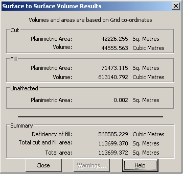
After viewing the Volume results click on Close. Now we will open the Height Difference File:
- Model the Height Difference Data Set
Select Task / Utilities / File / Open. Select the required File, i.e. "Final Volume.see"
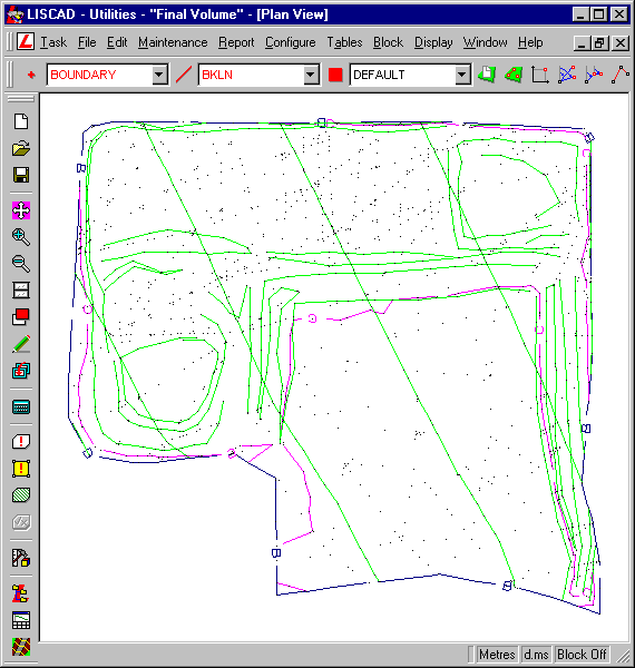
The first process is to check the Data set:
Click on Task / Terrain Modelling / Modelling / Validation. Select all the validation options to ensure that all errors are identified.
Select OK Carry out the Validation process and report any error conditions found.
Note: After the validation is completed, and if errors exist, the Validation Report dialog box enables you to view or print the errors by clicking the appropriate buttons. These errors should then be rectified using the appropriate menu commands in the Computations Task.
The most common error encountered as a result of creating a height difference data set is the possibility of duplicate points. If this occurs select Utilities / Maintenance / Filter Points.
Ensure the Filter X & Y Tolerance and Z Tolerance boxes are both crossed, enter a Tolerance of 0.001 for both, and select OK.
You may use the Form Model command without having validated the data base or corrected any errors but the model formed may then be incorrect.
Click on Modelling / Form Model. Search Distance of 100 and model named BASE, followed by OK.
Click on Display / Groups, click on None and then click on "Cutfill", followed by OK.
Click on Display / Features / Model and click on Contours and set the minor contour interval to 1.0 and the major interval to 5.0, followed by OK. This will display contours of height differences between the two models.
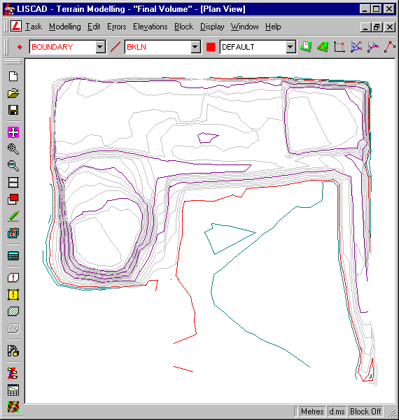
- Compute Volume Check Using the Height Difference Data Set
To get an independent check on the volumes switch to the Volumes Task and select Volumes/Base Plane. Enter a Datum Elevation of 0.0 and this will compute the volumes above and below the No Cut No Fill line.
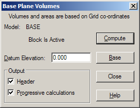
The volumes will not be exactly the same as that achieved from the previous Surface to Surface volume computation as the model formed in this data set is not the same as the previous two models. However the differences should not be large. In this case the difference between the cut and fill volumes using the two techniques is about 0.1%.
- Create a Point Grid Over the Height Difference Data Set
To facilitate the pegging of cut / fill stakes in the field, a grid can be imposed over the data set and heights interpolated for each point.
The points to be created will be given the attributes currently defined via the Attributes/Point command. Therefore we will set the required attributes before creating any points.
Set the Code Table to Tutorials -  Utilities/ Tables / Code Table / Open and select the "Tutorials" Code Table.
Set the Point Code attribute to GRID - Computations/Attributes/Point and set the Point Code as GRID.
To create the Grid Points click on Task / Computations / Create / Point and Method / Plane Grid
In the Create Points by Plane Grid Wizard key in an X direction of the Grid value of 0°. This means that the X axes of the grid will be vertically up the screen. Alternatively, you can snap to and accept existing points to define the x direction.
Type in the following coordinates for the Grid Origin - East = 825 & North = 1750 and select the Next button.
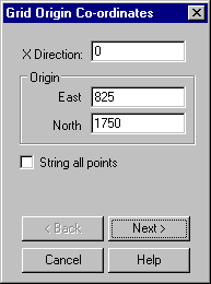
Please note that the Grid Origin can be anywhere on the grid area and that a point will not necessarily be created at these coordinates, it is a reference point only.
The Size X/Y item refers to ± X or Y distance that you wish to create grid points relative to the origin point of the grid.
Also, key in the interval the grid points will be placed at in the X & Y direction for the distance specified.
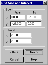
Set the required Grid Size and Interval Fields as shown and select the Next button when completed.
Specify that the point numbers will be generated automatically from what is currently in the system or from what is entered in the Point ID edit field by selecting the Auto-number radio button. Enter the starting Point ID as G3500.
Next select X precedes Y check box which means that the direction of the Point Numbers are going to run along the X axis.
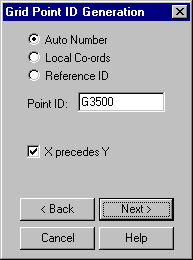
Select the Next button when completed.
Select the No Elevation radio button and accept the Finish button to create the plane grid of points.
Select Display/Features/Point tab, select Symbols and press OK to see the grid points created more clearly.
Select Display / Groups and select NONE and then click on the GRID group only and press OK
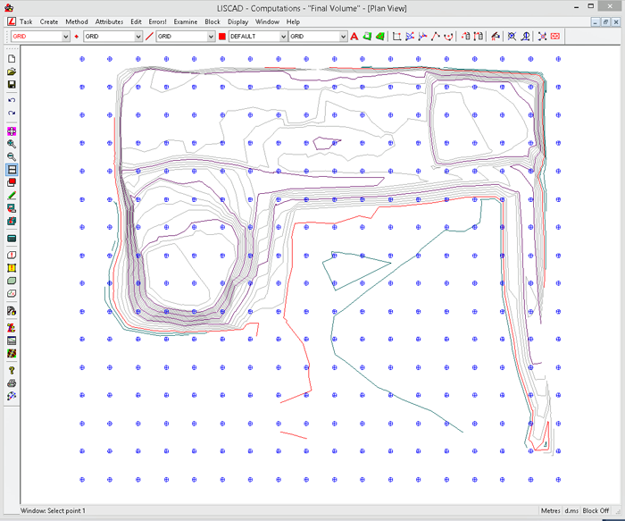
- Interpolation of Heights on to the Grid Points
To interpolate heights onto the grid points for set out:
Click on Block/Freehand and select All.
Select Task / Terrain Modelling / Elevations / Interpolate.
The Interpolate Elevation command interpolates the elevation of an existing point or points from the model, and stores the elevation against the point in the data base.
Check the Noncontourable box.
Check the Without elevations box.
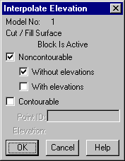
Select OK to interpolate an elevation onto each grid point.
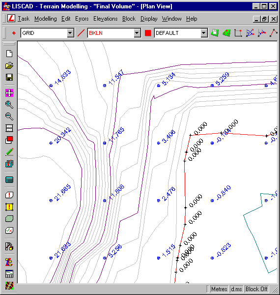
Note: After the interpolation option is finished, window in on an area of the data set and turn on Elevations
Display / Features / Points / Elevations
The positive / negative elevations shown are heights above or below design. The required data can be sent either directly to a data recorder for automatic set-out in the field.
- Clean-up Grid Points Outside the Model
We will now remove the grid points created that were outside the model and did not get an elevation.
Select Display / Groups and, holding down the Control key [Ctrl], select the GRID, BOUNDARY and DEFAULT groups only.Tick one of the box's highlighted to activate all highlighted.
Make sure that the polygon code is set to DEFAULT.

We will now create a polygon from the boundary string. Select Task/Computations/Create/Polygon, then Method/Element Selection. Now snap to and accept the boundary string and press End. This has created a polygon over the entire extents of the model. We can now use this polygon to construct a precise Block.
Select Block/Polygon and set the Region to Outside and the Condition to Enclosed. Turn OFF Include coincident points. Press OK.
Note: It is important to have Outside set as we want to delete all points outside of the model.
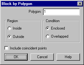
Now select Edit / Delete / Points.
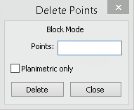
You will now be left with only the required grid points.
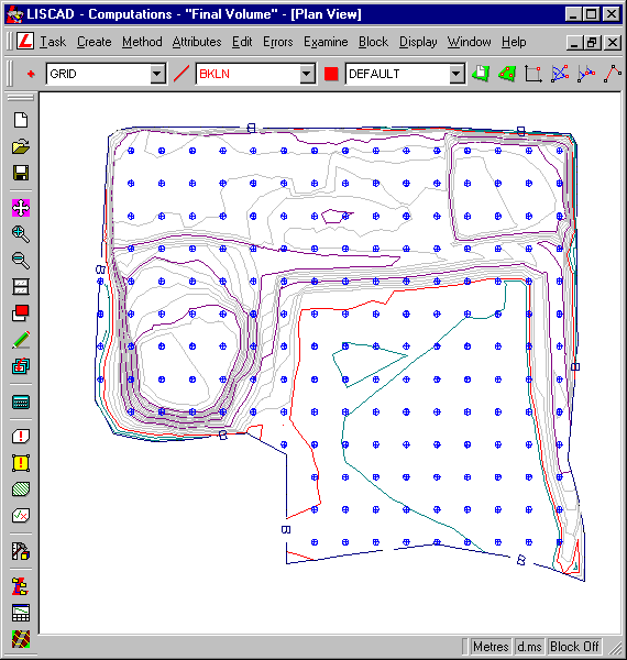
Conclusion
You have now completed this tutorial and should have a good understanding of how to calculate the volume between a natural surface and a design surface (Two Surfaces) and output grid points for field set-out.
You have also learnt how to:
- Create a height difference data set.
- Compute an independent volume check.
- Create points by plane grid method.
- Interpolate height of points without elevations.
- Create a polygon block.
- Clean up redundant data outside of the area of interest.