(This functionality is available with the Computations, Point Cloud and 3D Visualisation modules)
This dialog box is displayed after selecting the Attributes/Line command.
The dialog box is used to view or alter the current line attribute settings which will be used when line type objects are created in the Computations Task/Create commands. The various attributes and how to alter the settings are detailed below. Select any of these line attribute topics for their definitions.
When line objects are created in the data base using the Computations task, they are created with the attributes last set via this dialog box or via the Attributes/Adopt/Line command.
When you are satisfied with the attribute settings, select the OK button to save them as the current attributes. Alternatively, select the Cancel button if you do not wish to save them.
Line Attributes dialog box
| Item | Used to |
| Code Table | Select an existing code table. |
| Code: | Key in a feature code or select an existing feature code already defined
in the selected code table. The attribute settings are automatically changed to the settings stored in the code table for the selected feature code. Having feature codes already set up in the code table with the required attributes, and selecting the appropriate feature code in this field, is therefore the fastest and most convenient method of setting the required line attributes. Code tables may be set up and edited via the Utilities/Tables/Code Table commands. They may also be edited using the Update Code Table button in this dialog box. Altering the attribute settings in this dialog box will not alter the code table settings unless the Update Code Table button is used. Selecting an existing code previously defined in the code table is a quick method of setting the attributes. However, you may key in a code not contained in the code table and define the attributes as you wish. |
| Group: | Key in or select the group attribute. If a new group is entered, that group will be created when the OK button is selected. |
| Breakline | Toggle the breakline attribute. Lines with this attribute active may be used in model formation as change of grade lines. A line can only be a breakline if all points in the line are contourable. |
| Hard | A breakline may be either hard or soft. A hard breakline represents a sharp edge, such as a top of kerb whereas a soft breakline represents a more rounded edge, such as a river edge. If this attribute is active, the breakline is flagged as being a hard breakline. |
| Boundary | Toggle the boundary attribute. Lines with this attribute active will be used as boundary lines in model formation to define the inner or outer limits of the triangular model. Boundary lines must by definition also be breaklines. |
| View Convention | Set the view convention attribute. If this attribute is active, then the line dimensions will be displayed in directions which always make them readable from the bottom or right of the screen. If it is not active, then the dimensions will be displayed in the direction of the line to which they refer, and may therefore appear upside down on the screen. |
| Description: | Edit the line description attribute. The description may be up to 26 characters. |
| Colour: | Select the colour number attribute for lines. Note that the displayed line style in this dialog is always in the entity colour, and does not not reflect the colour number. |
| Curve Factor: | Set the curve factor attribute between 0 and 100. The curve factor governs the degree of curvature applied when splines are created. A lower curve factor will tend to create splines that are displayed with straight line segments, whereas a higher curve factor will tend to splines with all segments displayed as curved. Use a low curve factor to avoid nearby splines from illegitimately crossing each other. |
| Style... | Select the line style. Refer to the Line Style Library dialog box in Appendix 2. |
| Bearing | |
| Active | Toggle the bearing attribute. If active, lines created will have a bearing attribute. |
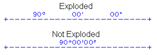
| Reverse | Reverse the bearing attribute by 180°. |
| Left | Position the bearing attribute left of the line as viewed in the direction of the line. |
| Right | Position the bearing attribute right of the line as viewed in the direction of the line. |
| Exploded | Spread the bearing out along the whole length of the
line segment.
 |
| Rounding: | Select the angle rounding. Three types of angle rounding (1, 2, and 3) are definable using the Utilities/Configure/Angles command. A setting of zero means that rounding will not be applied. |
| Distance | |
| Active | Toggle the distance attribute. If active, lines created will have a distance attribute. |
| Brackets | Toggle the brackets attribute. If active, distances will be enclosed in the bracket type selected in the Utilities/Configure/Distances command. |
| Left | Position the distance attribute left of the line as viewed in the direction of the line. |
| Right | Position the distance attribute right of the line as viewed in the direction of the line. |
| Rounding | Select the rounding for distance attributes. Three types of distance rounding (1, 2, and 3) are definable using the Utilities/Configure/Distances command. A setting of zero means that rounding will not be applied. |
| Distance type | |
| Along the line | Position the distance along the line, either above or below as specified. |
| Computed Offset | Position distances on the line. |
| Measured Offset | Position distances at the end point, perpendicular to the line, straddling the line, and facing the start point. |
| Chainage | Position the distance at the end point, perpendicular
to the line, left or right of the line, and facing
the start point. The example below shows the four distance types. Note that each line was created in a direction from left to right, the Distance Position was set to "Right", and View Convention was not active. 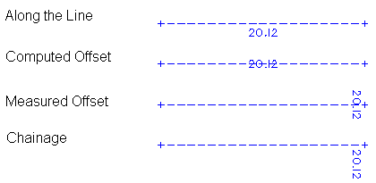 To view the various alternative distance positions, create a line with a distance attribute. While the rubber band is still attached, use the Attributes/Line command to select the various distance positions. Selecting the OK button in that dialog box will reflect the changes in the rubber banded line being created. |
| Arc/Circle | |
| Arc Distance | Set whether arcs are to have an arc distance shown. |
| Radius | Set whether arcs are to have a radius shown. If this attribute is active, and the Radial Radius attribute is inactive, the radius will be shown around the arc. |
| Tick Marker | Set whether arcs are to have tick marks at the arc end points. |
| Radial Radius | Set whether arcs are to have a radial radius
shown. If this attribute is active, the radius will be shown along the radial lines between the arc and the centre point. Clockwise Set whether arcs are to be created in a clockwise direction. |
| Anti Clockwise | Set whether arcs are to be created in an anti clockwise direction. |
| Above Arc | Set whether the radius is to be positioned above the arc. |
| Below Arc | Set whether the radius is to be positioned
below the arc. Refer to the diagram below for an example of the arc/circle settings.  Exaggeration
 |
| Exaggeration | Set whether the exaggeration attribute
is to be used. Set this attribute if you are creating an offset or radiation object, the length of which is required to be increased in any CAD file created from the system. This feature is very useful if "not to scale" drawings are to be produced. Points which are very close together can be separated for the purpose of clarity when the CAD file is created. |
| Factor | Set the exaggeration factor to be
used. If an offset object or radiation object has an exaggeration factor, its size will be increased by that factor in any CAD file created from the system. The end point of the offset or radiation will be shifted in the CAD file and no longer be in its true position. However the offset and distance values will be passed to the CAD file unchanged. |
| Alignment | |
| Stacked | Set whether the bearing and distance attributes are to be shown one above the other. |
| Aligned | Set whether the bearing and distance attributes are to be shown side by side instead of stacked |
| Relationship | |
| Distance on Line | Set whether the distance attributes are to be shown nearer to the line than the bearing attributes for stacked bearings and distances. |
| Bearing on Line | Set whether the bearing attributes are to be shown nearer to the line than the distance attributes for stacked bearings and distances. |
| Distance to Left | Set whether the distance attributes are to be shown left of the bearing attributes for aligned bearings and distances. |
| Bearing to Left | Set whether the bearing attributes
are to be shown left of the distance
attributes for aligned bearings and
distances. The alignment/Relationship settings cannot be used unless the bearing and distance position settings are both left or both right. Following are two examples of Alignment/Relationship settings. Both lines have been created in a direction from left to right. In the first example, the bearing and distance are both in Position "Left", alignment is set to "Aligned" and relationship is set to "Bearing to Left" In the second example, the bearing and distance are both in Position "Right", alignment is set to "Stacked" and relationship is set to "Distance on Line"  |
| Update Code Table | Changes the line attribute settings
in the selected code table for the
selected feature code, to reflect
the settings currently shown in this
Line Attributes dialog box. This is a convenient method of editing the code table without the need to use the Utilities/Code Table commands. If the change is to an existing feature code in the code table, rather than the addition of a new feature code, a warning dialog box will be displayed asking that you confirm the operation. |
| OK | Close the dialog box and save any changes as the current line attribute settings to be used when new line objects are created. |
| Cancel | Close the dialog box without saving any changes to the current line attribute settings. |